background image

53

Wuhan Raycus Fiber Laser Technologies Co., Ltd.

User Guide of RFL-C20000M-CE

8.4. Laserparameterdisplayarea

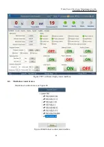
The display interface for laser parameter display area is as Figure 37. The module status is used to

shield the faulty module, the green light indicates the number of modules installed inside the current laser,
and the check box indicates the module that is actually running in the current laser.

Figure 37Laser parameter display area display interface

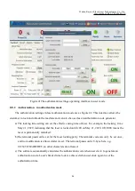
8.5. Alarm type display area

The laser alarm type display area interface is as Figure 38. This interface shows the cause of the

alarm for the current laser.

Figure 38Laser alarm type display area interface

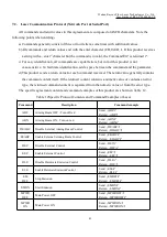
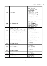
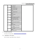
8.6. PC softwareoperatingmodeselection

The laser operating mode is set by the PC software. Its operating interface is as Figure 39. The

interpretation of the various patterns can be found in Table 16. The programming editing interface is
displayed on the software only when programming mode is selected.

Summary of Contents for RFL-C20000M-CE

Page 1: ...Global Version RFL C20000M CE Continuous Wave Fiber Laser User Guide WuhanRaycusFiberLaserTechnologiesCo Ltd...

Page 2: ...utput cable and using description 11 3 3 1 Types of protective end caps and factory status 11 3 3 2 Pre installation cleaning instructions for output cables 12 3 4 Cooling Requirements 14 4 Using the...

Page 3: ...ode 39 7 RS232 and INTERNET communication command 40 7 1 Port Configuration 40 7 2 Laser Communication Protocol Network Port Serial Port 41 8 PC software instructions 45 8 1 Maininterface of PC softwa...

Page 4: ...11 3 Downloaded file address 61 8 12 Module parameters in diagnostic mode 61 8 13 Programming settings programming editing 61 8 13 1 View the number of wave bars inside the current laser 62 8 13 2 Ch...

Page 5: ...information Please read the manual carefully before using this product To ensure safe operation and optimum product operation please observe the following cautions and warnings as well as other infor...

Page 6: ...r radiation at a wavelength of 1080 nm or around 1080 nm and the average laser power radiated from the output head is 20 kW Direct or Indirect exposure to high power laser radiation causes damage to t...

Page 7: ...re that the AC voltage is supplied normally CAUTION Wrong wiring mode or power supply voltage will cause anun recoverable damage to the laser device 1 5 Other Safety Rules a Do not view the laser outp...

Page 8: ...igned packaging materials and cabinets Raycus ensures that the lasers are fully protected during transportation Nevertheless in order to prevent unpredictable situations during transportation the user...

Page 9: ...appropriate lens paper to clean it ifnecessary c Failure to follow the instructions when operating the laser may cause malfunction and damage d It is not allowed to install the output head when the la...

Page 10: ...output Types QP Beam Quality BPP mm mrad 3 5 4 3 1 e2 Nominal Output Power Fiber core diameter m 100 customizable Delivery Cable Length m 30 customizable Electrical characteristics Operating Voltage T...

Page 11: ...7 Wuhan Raycus Fiber Laser Technologies Co Ltd User Guide of RFL C20000M CE Figure 2 a Front and rear view of the laser...

Page 12: ...continuous fiber laser uses the RFL QP output optical cable and the external dimensions of the output optical cable head are shown in Figure 3 Figure 3 External dimensions of the RFL QP output optical...

Page 13: ...n ofthe output optical cable to avoid damage to the optical fiber g In the process of installing the optical cable output head ensure the cleanliness of the surrounding environment do not use electric...

Page 14: ...1 The placement of the laser output cable should be as natural as possible and the output cable should not be twisted 2 If the coil diameter ofthe output optical cable is too small it will damage the...

Page 15: ...is generally packed in a lamination box The end cap is not equipped with a protective window which is used to prevent the end cap from being damaged when the optical cable is loaded with the cutting...

Page 16: ...k packaging box Figure 6 Output cable placed in the box c Place the output optical cable in a clean workbench Note The following operations need to be carried out in a clean workbench If the operation...

Page 17: ...in qq com s hRXrPkb8DAyvDYegSWwYLg Note The end cap cleaning is generally performed by our professional staff If the customer needs to operate it by himself we need to go through the relevant training...

Page 18: ...as shown in order to facilitate there transportation of the laser or output cable Note The fiber optic cable must be loaded with Type A end caps each time it is transported That is every time the out...

Page 19: ...alcohol volume ratio and replace it every 2 months e If ambient temperature is below 10 the chiller with both heating and cooling functions must be used and keep it in full time operation f For the c...

Page 20: ...bending radius in non working conditions such as transportation and storage the minimum bending diameter shall not be less than30cm When the laser is emitting the minimum bending diameter shall not be...

Page 21: ...e main control part of the laser is powered on and the POWER light is on Rotate to the REM position you need to close the 8 and 9 pins of the XP2 interface on the rear panel to realize remote power on...

Page 22: ...OP Emergency stop button press to turn off the main power of the laser immediately turn the button clockwise to release the button and press the LASER button again to start the main power of the laser...

Page 23: ...tput optical cable water outlet this interface is connected to the output optical cable water inlet connected to the 13 inner diameter water pipe WATER OUT The water outlet of the laser this interface...

Page 24: ...RING XP1 Security interface Analog interface Serial interface Communication Interface XP5 Figure 14 Control signal line 4 4 1 Safety XP2 Interface 24 pin safety interface with remote control system po...

Page 25: ...put contact passive contact current 100mA voltage 30V If the current panel stop pressed pin 12 and pin 13are open or else close 13 OUT 15 OUT FET S pole Main power supply power on output indication MO...

Page 26: ...000000 and the A6 is high A3 Enabling Internalpatter Input signal High level enables PC software control function A4 reset signal Input signal Active on rising edge to clear laser alarm bit effective...

Page 27: ...rol mode when B3 is high In this mode the laser can be controlled by communication B4 Laser anomalies Output signal The laser is abnormal when B4 is high B5 Laser red light indication Output signal Th...

Page 28: ...tical gate channel Output signal D5 Not connect D6 Not connect D7 QCW mode Output signal Output signal indicating that the current laser operates in QCW mode For lasers with QCW mode only D8 D11 Laser...

Page 29: ...Reference Ground for High Backup Voltage 4 4 5 INTERNET Interface XP5 Table 10 XP5 Communication interface definitions Pin Function Description 1 TX Data transmission 2 TX Data transmission 3 RX Data...

Page 30: ...rcuit is open or the error is detected the main power supply of the optical module will be turned off and the main power supply has been started signal ofthe interface will become low level The detect...

Page 31: ...rs and 6 signal terminals are used in series 4 7 Start operation sequence a Turn on the water cooler check whether the water pipe is leaking turn offthe water cooler and connect electrically b Make su...

Page 32: ...h start the main power supply waiting for the laser to Ready the laser Ready the tricolor green light above the machine representing that the laser can light 5 Control Mode Selection The Raycus high p...

Page 33: ...the host computer software Send DLE by communication or click button on the host computer software Send EEC by communication or click button on the host computer software Send ELE by communication or...

Page 34: ...software or direct communication After the laser is powered on again the mode before power failure will be memorized 5 2 AD Enable Mode When AD mode is enabled the laser power is determined by the an...

Page 35: ...0 the laser runs in the Programming mode Please use the Raycus Host Computer Software to edit the waveform and select the pre run program number When the laser is in the internal control mode Send the...

Page 36: ...mode andthe red light is controlled by the computer software red light button or through communication by sending ABN or ABF command to control the ON OFF of the red light When A1 of XP1 is set high...

Page 37: ...key switch at ON position Operations Steps a Turn the knob switch on the rear panel to ON b Turn the key switch to ON c Open the Raycus Laser Control System d Click the guide laser ON button to view t...

Page 38: ...e knobswitch on the rear panel to ON b Turn the key switch to ON c Open the Raycus Laser Control System d Click the guide laser ON button to view the guide laser e Turnoff AD mode and turn on External...

Page 39: ...by analog signal Operations Steps a Turn the knob switch on the rear panel to ON b Turn the key switch to ON c Open the Raycus Laser Control System d Click the guide laser ON button to view the guide...

Page 40: ...switch to ON c Open the Raycus Laser Control System d Click the guide laser ON button to view the guide laser e Click the main power ON f Waiting for Ready g Set the pre executed waveform number the...

Page 41: ...1 A5 to 24V and turn on the guide laser after checking the optics connect XP1 A5 to 0V and turn off the guide laser f XP1 C1 is connected to 24V and the main power is turned on operator can also direc...

Page 42: ...Communication Setting in REM Raycus Laser XP1 Hardwiring XP2 Security Interface 1 2 8 9 17 18 19 20 AC INPUT Figure 22Wiring diagram ofpower internal control and laser emission external Peripheral AC...

Page 43: ...24V and the main power is turned on users can also directly press the LASER button or the host computer software clicks the main power ON g Waiting for Ready h The Raycus Laser Control System sets the...

Page 44: ...connected to 24V and the main power is turned on users can also directly press the LASER button or the host computer software clicks the main power ON g Waiting for Ready h XP1 A8 14 select the number...

Page 45: ...f If the returned content contains a numeric value or contains an error type the returned command content is separated from the numeric value or from the error type The specific agreement content and...

Page 46: ...rent The set value must be less than 100 and above the minimum current setting value which can be set to 0 If the set value is greater than 100 the default is input 100 Send SDC 100 r Return SDC 100 r...

Page 47: ...analog response time is less than 100 us in this mode Send DCM r Return DCM r Others Command error Send BGM r Return Command Err r STA Read device status Read the product status A return value of 32...

Page 48: ...e on Bit 11 Module Main Power off Module Main Power on Bit 12 Modulation mode off Modulation mode on Bit 13 normal Leakage sensors 1 leaking Bit 14 normal Leakage sensors 2 leaking Bit 15 No laser Las...

Page 49: ...wmeter 1 Flow Alarm Bit 27 Red light internal control Red Light External Control Bit 28 normal Water flowmeter 2 Flow Alarm Bit 29 normal Module locked Bit 30 Optical circuit safety interlock normal O...

Page 50: ...iber Laser Technologies Co Ltd User Guide of RFL C20000M CE Figure 25PC software display main interface 8 2 Multi laser control area Multi laser control area is as Figure 26 Figure 26Multi laser contr...

Page 51: ...e lower left status display shows that the network connection is ok as Figure 27 Figure 27 communication status interface between PC software and laser 8 2 1 Add delete laser You can add delete laser...

Page 52: ...E 8 2 2 ModifylaserIP After the laser connection has established select the IP address of current laser and right click to set it up as Figure 29 Figure 29Modify the IP address of laser 8 3 Main worki...

Page 53: ...green laser is ready gray laser is not ready Alarm light indicates alarm status of current laser yellow laser is abnormal gray laser is normal Emission light indicates the working model of the current...

Page 54: ...cally adjusts the laser s output power It makes the output power linear with a longer response time for AD analog in this mode longer than 1mS Gray laser operates in non correction mode and the extern...

Page 55: ...ode power off memory automatically AD mode Click ON AD analog mode on click OFF AD analog mode off mode power off memory automatically Red guide beam Click ON red guide beam on click OFF red guide bea...

Page 56: ...ting parameters to set a new power rise and fall time When the rise and fall times are set to 0 the power slow rise fall function is automatically switched off When there is no 0 the slow rise or fall...

Page 57: ...in the current laser Figure 37Laser parameter display area display interface 8 5 Alarm type display area The laser alarm type display area interface is as Figure 38 This interface shows the cause ofth...

Page 58: ...explanation Mode selection Mode explanation Monitor A concise software interface which can monitor basic status information Control Supports the selection of control modes such as AD mode external co...

Page 59: ...interface is as figure 40 User can choose between Chinese simplified and English by click setting language Setting effective after PC software restarted Figure 40 Language selection interface 8 8 Auth...

Page 60: ...e effective using time of laser For example the locking time May 21 2020 indicating that the laser is locked until 0 00 on May 21 2020 0 0 2000 means the laser is permanently unlocked b The terminal p...

Page 61: ...ettings operating interface in authorization mode 8 9 About Laser relevant information such as date of manufacture model serial number controling serial number token version number system information...

Page 62: ...levant information query interface 8 10 XP1 interface status indication in diagnostic mode The laser interface status indicator interface is as Figure 44 It is convenient to view the interface status...

Page 63: ...FL C20000M CE Figure 44 The interface status in diagnostic mode 8 11 Log in diagnostic mode Laser s working log interface is as Figure 45 User can query work log by entering the time to query and clic...

Page 64: ...f RFL C20000M CE 8 11 1 Download log Log download interface is as Figure 46 Figure 46 Log download interface 8 11 2 Downloadrecord of historicalfault Historical fault record download interface is as F...

Page 65: ...e for all downloaded information 8 12 Module parameters in diagnostic mode Laser module parameter query interface is as Figure 49 The interface is for the parameter query in diagnostic mode from which...

Page 66: ...t laser Operating interfaces of view the number of wave bar stored inside the current laser is as Figure 51 The software automatically lists the number of wavelength bars that have been saved by click...

Page 67: ...rammings by click the programming number that needs to be checked Figure 52Programming content interface in the current laser programming mode 8 13 3 Empty all waveforms Empty all programming interfac...

Page 68: ...pre edited programming number Step 2 select the command under the command type click Add Step 3 enter the parameters and click Save The instruction appears in the left program list immediately Step 4...

Page 69: ...65 Wuhan Raycus Fiber Laser Technologies Co Ltd User Guide of RFL C20000M CE b add command type c save command...

Page 70: ...Guide of RFL C20000M CE d type the command code into laser e check effectiveness of instruction Figure 54A diagram of the programming editing operation in programming mode 8 13 5 Command explanation C...

Page 71: ...nge power to 2 in power change ratio 1 4 WAIT 1 Wait for sync signal low level Null 2 Wait for sync signal high level Null 3 Wait for sync signal rising Null 4 Wait for sync signal droping Null 5 Wait...

Page 72: ...caused by those who are not from Raycus Thecustomer has the responsibility to understand and follow this instruction to use the device Any damage caused by fault operating is not warranted Accessorie...

Page 73: ...l specifications Raycus reserve the right to make changes in design or constructions of any of our products at anytime without incurring any obligation to make changes or install the same on units pre...

Reviews: