55M4000BCE00 REV A
20
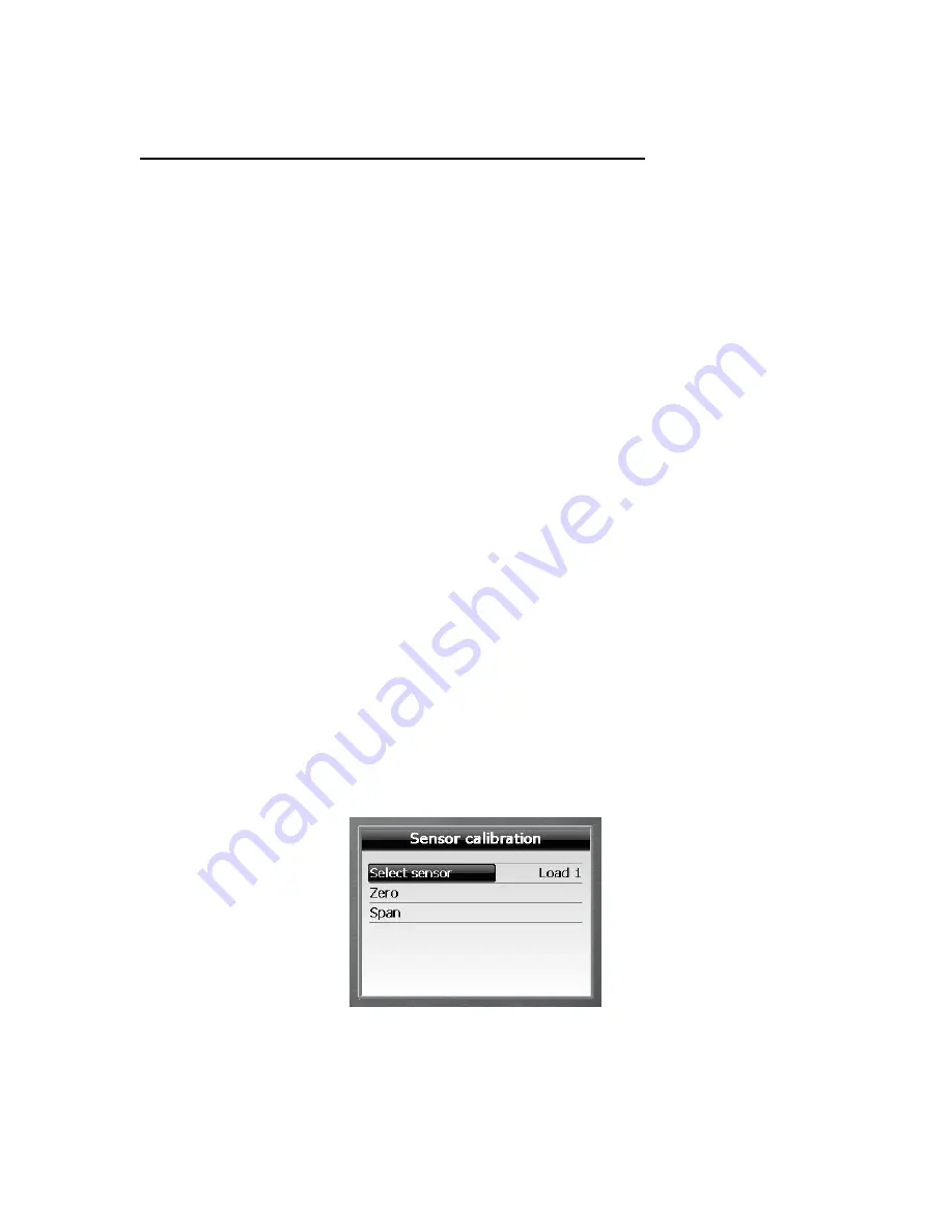
3.3 Step #11: “Zero load/Span load” sensor calibration
When calibrating load sensors, always slowly hoist and stop the test loads smoothly in
order to eliminate errors in the load reading due to frictional effects. The frictional
effect on dynamometer (line rider) systems will cause the displayed load to decrease
when lowering the load and to increase when hoisting the load. On dead-end load cell
systems this effect is reversed. These friction effects can be minimised by ensuring
boom head sheaves and hook block are in good condition and properly maintained
before proceeding.
Warning:
The system does not store the ZERO LOAD into permanent memory until the
SPAN LOAD calibration has been completed. If a ZERO LOAD calibration is done, then a
SPAN LOAD calibration must also be done.
Load sensor calibration must be done with two, accurately known test loads, a small
load and a large load. The large calibration load should provide between 50-90% line
pull on the hoist line while using as many parts of line as is feasible. If a large enough
load cannot be found, the crane can be reeved to fewer parts to increase the line pull
for a given calibration load. The smaller load should be approximately 5-10% of the
larger load and in many cases the block weight alone may be sufficient. The calculated
test loads should normally include the weight of the hook block and any slings, shackles
etc. that are used.
Note: The system must use the part of line currently rigged on the block in the load
value calculation, this value is set in the normal mode, make sure that this value is
conform to the number of part of line currently rigged on the block. If it’s not the case
you must adjust it in the normal mode.
Select the load sensor to be calibrated
1)
Use
“
”
or
“
”
to choose “Select sensor” and press
“
”
.
2)
Use
“
”
or
“
”
to select the relevant load sensor and press
“
”
.


