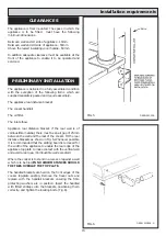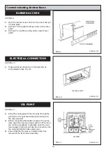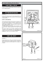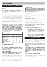
SEE FIG. 2
The flue system must be installed with the regulations in
force.
Information
Maximum flue gas temperature 260˚C
(Both burners on)
Minimum flue gas temperature 125˚C
(Boiler burner on only)
The appliance requires a minimum chimney draught of
1.0mm (0.04 WG) with both burners on.
Maximum chimney draught 6.0mm (0.23” WG) draughts
in excess of this figure will require a draught stabiliser,
fitted either in the chimney or flue pipe and in the same
compartment.
Flue gas mass flow (Both burners on) - 460K-111.5 kgh
-1
480K - 95.5 kgh
-1
499K - 185 kgh
-1
Detailed recommendations for flueing in England and
Wales are given in Part J of the Building Regulations. For
Scotland in Technical Standard F to the Building
Standards and in Northern Ireland in Technical Booklet L
to the Building Regulations. Guidance is also given in BS
5410: Part 1.
Due to the range in flue gas temperatures a brick
chimney should be fitted with a suitable multifuel
stainless steel flexible liner. Where it is necessary to
avoid condensation, such as an exposed end gable
insulation; such as vermiculite, should be back filled
between the flexible liner and the full length of the
brickwork.
NOTE: TO ACHIEVE THE OPTIMUM OPERATIONAL
SOUND LEVELS FROM THE APPLIANCE IT IS
RECOMMENDED THAT CAST IRON FLUE PIPE IS
USED WHERE POSSIBLE.
Chimney Termination
All chimneys should terminate at least 600mm above the
roof level in accordance with current Building Regulations
and statutory requirements as outlined in BS 5410: Part 1,
BS 6461: Part 1 and BS 7566 Parts 1 to 4.
Chimney Cleaning
Ensure there are accessible airtight flue cleaning doors in
order to obtain cleaning access to the complete chimney.
Providing the appliance is operating correctly, an annual
chimney flue cleaning will suffice, but if in doubt arrange
for a half yearly clean, preferably at the beginning/end of
the heating season.
Site requirements
8
FLUE SYSTEM
FIG. 2
DESN 510521’A’
Summary of Contents for Heatranger 460K
Page 16: ...14 Site requirements FIG 4 460 480 499 K...
Page 19: ...Installation requirements 17 FIG 8A...
Page 26: ...24 Sealed System FIG 18...
Page 27: ...25...
Page 28: ...26...
Page 29: ...27...


