The appliance is delivered in a fully assembled condition
with the exception of the following items which are
supplied separately packed and require assembly.
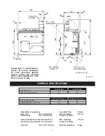
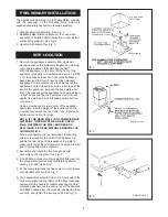
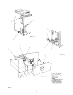
1. Draught Diverter Assembly - See Fig. 3.
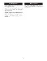
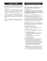
2. Appliance Rear Distance Bracket - (For use when
appliance is installed 25mm away from a rear wall of
combustible material). See Fig. 4.
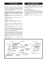
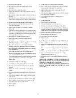
3. Handrail & Brackets. See Fig. 5.
1. Remove the appliance assembly from its transit
wooden pallet by the temporary location of a sloping
ramp board between the pallet and the floor.
With the appliance on the floor, lift the front of the
appliance (manually or crowbar) and insert a 1in BSP
x 1m long tube between the front of the appliance
base plate and the floor. Draw the tube balanced
appliance forward until the tube is at the rear of the
appliance and then insert a second similar tube at the
front of the appliance, between the base plate and
floor. The tube supported appliance can now be slowly
“rolled” across the floor and positioned with its back
against the wall, and in its intended position for flue
connection.
Using a crowbar at the rear corner of the appliance
base plate, take the weight of the appliance on the
crowbar and remove the rear roller tube, followed by
similar action on the front tube.
NOTE: IF THE REAR WALL IS OF COMBUSTIBLE
MATERIAL, THERE MUST BE AN AIR GAP OF
25mm BETWEEN THE WALL AND REAR OF
APPLIANCE. FIT REAR DISTANCE BRACKET AS
SHOWN IN FIG. 4.
Wherever possible, it is recommended that skirting
board is removed for the width of the appliance to
enable the rear edge of the appliance top-plate to
make contact with the vertical wall, and avoid a rear air
gap (Combustible walls excepted).
2. Assemble and locate the flue draught diverter
assembly on the top plate. See Fig. 3.
3. Fit a 600mm minimum vertical height of flue pipe into
the draught diverter flue socket before any bends,
sealing joint with fire cement.
4. Connect and terminate the flue system in accordance
with standard practice. See Fig. 1.
5. The handrail brackets are held on the front ends of the
cooker top-plate casting. Remove the travel nuts and
replace with the handrail brackets ensuring the fibre
protecting washers are in position. Insert the handrail
with fitted endcaps into the brackets, positioning them
correctly, and tighten the locating bolts. See Fig. 5.
8
PRELIMINARY INSTALLATION
SITE LOCATION
FIG. 3
FIG. 4
FIG. 5
DESN510454 ‘A’


