background image

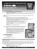
AJ-24 SPEAKER STAND

Easy Assembly Instructions

May we take this 

opportunity to thank 

you for purchasing the 

AJ-24 speaker stand. 

We strongly suggest 

that you carefully 

study these assembly 

instructions before 

attempting to assemble 

the unit, and that you 

observe the listed 

precautions.

R

CAUTION

SUITABLE FOR SMALL TO MEDIUM SIZE SPEAKERS. 

DO NOT OVERLOAD THE STANDS. 

Contact the Acoustic Solutions Helpline on 01327 340601 for any replacement items. This line 

is manned from 9:00am until 4:30pm, Monday to Friday.

REV: 1/046/1.3 

Please read these precautions before assembling and using this unit.

                  Take care when unpacking to avoid damaging parts.

                  Do not overtighten the wood screws.

                  Do not use abrasive cleaners, use only a damp cloth to clean.

1
2
3

Summary of Contents for AJ-24

Page 1: ...ed precautions R CAUTION SUITABLE FOR SMALL TO MEDIUM SIZE SPEAKERS DO NOT OVERLOAD THE STANDS Contact the Acoustic Solutions Helpline on 01327 340601 for any replacement items This line is manned from 9 00am until 4 30pm Monday to Friday REV 1 046 1 3 Please read these precautions before assembling and using this unit Take care when unpacking to avoid damaging parts Do not overtighten the wood sc...

Page 2: ...piked feet 8 F Isolation pads 8 Tools needed Pozidrive screwdriver not included A B C D C E F Please Note Specifications of parts are subject to change without notice E OE Remove all parts from the carton and inspect them If you find any damaged or missing parts please contact the Acoustic Solutions Help Line on 01327 340601 for replacements This line is manned from 9 00 am until 4 30 pm ...

Page 3: ...umn sides Using 4 wood screws align the holes in the base plate with the pre drilled holes in each column side plate Note that the rounded edges of the column side plates should face the front wider edge of the base plate Tighten screws evenly 4 Using 4 woodscrews align the holes in the top plate with the pre drilled holes in each column side plate Tighten screws evenly 2 3 5 5 Fit 4 self adhesive...

Page 4: ...op and bottom of the cable cover strip as shown in 8A or through the hole in the base plate as shown in 8B Ensure the speakers are balanced on the stands 8 6 Fit 4 spiked feet E into the holes in the bottom of the base plate The spiked feet are threaded it is necessary to screw them into the corresponding holes on the base plate The spiked feet are optional to provide isolation between the stands ...

Reviews: