background image

 SmarTrax & QuickTrax Operation Manual

2 0

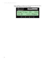
When Calibration is complete, the console will beep and the home screen 

will display. SmarTrax is now ready to operate. 

Summary of Contents for SmarTrax

Page 1: ...SmarTrax QuickTrax Operation Manual P N 016 0159 956 Rev H 09 15 Copyright 2009 2015...

Page 2: ...en Industries cannot guarantee the accuracy integrity continuity or availability of the GPS signal from the U S Department of Defense NAVSTAR GPS satellites the OmniSTAR correction service or the WAAS...

Page 3: ...cer 6 TM 1 Tilt Sensor 7 Chapter 3 Setting Up and Starting the SmarTrax QuickTrax Systems 9 Initial Start up 9 Sensor Type 9 SPS Sensor Setup 10 Yaw Sensor Set up 15 Hydraulic Calibration 19 Troublesh...

Page 4: ...34 Antenna Position 35 Setting the Antenna Correction 35 Press the Left or Right arrow until the measured value is displayed 35 Antenna Height 35 Steer Pulse Time 36 Setting the Steer Pulse Time 36 GP...

Page 5: ...ual 016 0159 956 i i i Error Log 47 GPS Date and Time 47 Yaw Rate 48 Time VS Inch Status 48 Average Speeds 48 Chapter 6 Troubleshooting 49 Error Messages 49 Mechanical Problems 52 Operational Problems...

Page 6: ...SmarTrax and QuickTrax Operation Manual i v...

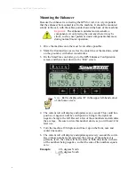
Page 7: ...that determines the location of the machine in the field The system calculates where the equipment should be located by referring to the swath path set by the operator and the actual location of the...

Page 8: ...SmarTrax QuickTrax Operation Manual 2 Notes...

Page 9: ...ler as shown below SmarTrax Controller Controller Modes The SmarTrax controller has three possible modes that it can be in The mode will appear in the upper right corner of the home screen Two of the...

Page 10: ...the speed to below 27 0 mph or the SmarTrax steering will disengage If the speed reaches 29 mph the SmarTrax system will disengage and all lights will flash until the steering wheel is turned If the...

Page 11: ...x system to accurately hold the line in decimetric mode by removing variations due to antenna movement from the GPS data stream By removing antenna motion overall system accuracy is greatly improved G...

Page 12: ...positive being to the right and negative being to the left Record a few of these numbers and calculate the average Be sure to write this number down as you will need it for later use 5 Turn the machi...

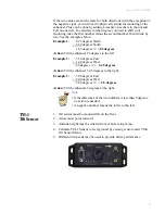
Page 13: ...er 82 degrees to the left Example 2 5 50 degrees East 1 40 degrees West 6 9degrees 2 3 45 degrees Action Tilt the enhancer 3 45 degrees to the right Example 3 3 00 degrees East 2 00 degrees West 5 00...

Page 14: ...SmarTrax QuickTrax Operation Manual 8 Notes...

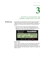
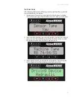
Page 15: ...initial start up the SmarTrax controller will prompt you to answer Yes or No to having read and understand the Operation Manual Answer either Yes or No To continue with start up you must answer Yes by...

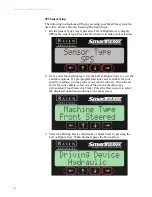
Page 16: ...n 2 Next select the machine type Use the Left or Right arrows to view the available options If a pre programmed tune set is available for your specific machine you may select your vehicle tune set If...

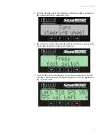
Page 17: ...witch to continue start up 5 Press the foot switch The controller will need to detect a change in the foot switch position to continue with start up 6 The Left SPS Cal screen displays To set the Left...

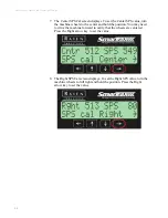
Page 18: ...s to the center and hold the position You may need to drive the machine forward to verify that the wheels are centered Press the Right arrow key to set the value 8 The Right SPS Cal screen displays To...

Page 19: ...ter 5 for measurement instructions When you are finished press the Down arrow to save the displayed setting Important The following measurements are critical for proper and accurate operation of your...

Page 20: ...aft position of the GPS antenna with respect to the rear axle If the GPS antenna is in front of the rear axle enter a positive value for this setting When you are finished press the Down arrow to sav...

Page 21: ...arrow to display Yaw as the sensor type Press the Down arrow to make your selection 2 Next select the machine type for your machine Use the Left or Right arrows to view the available options Press the...

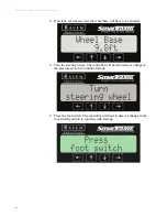
Page 22: ...e wheelbase will have to be entered 5 Turn the steering wheel The controller will need to detect a change in the pressure switch to continue start up 6 Press the foot switch The controller will need t...

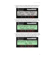
Page 23: ...your SmarTrax controller Press the Left or Right arrow to select either Feet Decimal Feet Inches or Metric Press the Down arrow to set the value 9 Use the Left or Right arrows to program the fore or a...

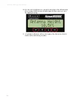
Page 24: ...t or Right arrows to program the height of the GPS antenna above ground When you are finished press the Down arrow to save the displayed setting 11 A hydraulic calibration will now be required See the...

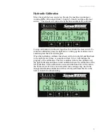
Page 25: ...screen and then press the foot switch again When the hydraulics calibrate the wheels will turn to the left and then back to the right several times A countdown from 10 to 2 will indicate the progress...

Page 26: ...SmarTrax QuickTrax Operation Manual 2 0 When Calibration is complete the console will beep and the home screen will display SmarTrax is now ready to operate...

Page 27: ...ew calibration will be necessary Steer Switch Activated If the steer switch is continually being engaged the steer pulse time can be altered To do this press down from the steer switch screen Then pre...

Page 28: ...SmarTrax QuickTrax Operation Manual 2 2 Notes...

Page 29: ...he GGA and VTG messages are turned on at 1 seconds 10 Hz Refer to the RPR 210 310 manual for more information Phoenix 300 Starting the Receiver After start up of the Phoenix 300 an R must be present i...

Page 30: ...Hz 1 seconds ZDA 2 Hz 5 seconds Enhancer Configuration Enhancer configuration can be done by accessing the GPS Enhancer Configuration menu screen on the SmarTrax controller You can only access this m...

Page 31: ...n Sections The Home screen is split up into four sections as shown above the upper left section SmarTrax OK the upper right section OnL the lower left section v4 0 and the lower right section 11 5Mph...

Page 32: ...m the Home screen navigate to the following screens by pressing the Down arrow Aggressiveness Line Acquire Sensitivity OnLine Aggressiveness Line Acquire This screen adjusts the performance when acqui...

Page 33: ...ity OnLine This screen adjusts the sensitivity of the on line performance This value can be adjusted between 1 and 20 The higher the value the more aggressive the machine is on line Use the Left and R...

Page 34: ...Setup GPS Enhancer Configuration only accessible if the GPS Enhancer is detected Tilt Sensor Configuration only accessible if the tilt sensor is detected Console Configuration Status Menu From the Hom...

Page 35: ...on cannot be changed View Sensor Type Left Center and Right SPS or Yaw Calibration Zero Yaw Rate if Yaw Sensor is installed Wheel Base Minimum Turning Radius if SPS is selected Antenna Position Antenn...

Page 36: ...or QuickTrax This is a display only Sensor Type The Sensor Type screen displays the type of sensor for which SmarTrax is currently calibrated This is a display only Note If Yaw is selected on this sc...

Page 37: ...on The Center SPS Calibration screen displays the calibrated center wheel position of the vehicle as well as the current SPS count To set the Center SPS Calibration slowly drive the vehicle forward as...

Page 38: ...ng verify that the current SPS values are changing Once you have reached the full right position press and hold the Right arrow to program the value into the controller Zero Yaw Rate If you have selec...

Page 39: ...system to steer properly Measuring the Wheel Base 1 Measure the wheel base of the vehicle This is the distance from the center of the front axle to the center of the rear axle 2 Press the Left or Rig...

Page 40: ...Center Method to determine the minimum turning radius for your machine 1 Drive the vehicle in the tightest possible circle 2 Measure the diameter between the center of the front wheel tracks See the...

Page 41: ...eft or Right arrow until the measured value is displayed Antenna Height Antenna height is a critical value that will need to be measured and entered into the controller This value is the height from t...

Page 42: ...This setting displays in milliseconds ms and represents the amount of time that the controller must read a high pressure spike before disengaging the system If the system disengages while traveling t...

Page 43: ...appear on the SmarTrax controller menu between the Vehicle Setup and Console Configuration Note This menu screen is only available if you are using a GPS enhancer Important You must have GPS messages...

Page 44: ...y every second and is used to verify that the GPS Enhancer is mounted level Refer to the Mounting the Enhancer section in Chapter 2 for more information Roll pitch and heading are displayed in degrees...

Page 45: ...cer menu options is the Firmware Version screen This screen displays the current firmware version running on your enhancer Reset Enhancer Press the Right arrow button to reset the GPS Enhancer 1 Press...

Page 46: ...finished setting the status press the Down arrow to continue TM 1 Tilt Sensor Configuration The TM 1 Tilt Sensor Configuration Menu screen allows you to change or set configurations for the TM 1 Tilt...

Page 47: ...the sensor Zero Tilt Angle The Zero Tilt Angle screen allows the tilt sensor to be calibrated for zero angle or level ground To set the tilt sensor zero drive the machine on to level ground and press...

Page 48: ...console see list below for configurations you can set LCD Back Light LCD Contrast Distance Units Speed Units Output Key Beep Serial Number Lockout Settings LCD Backlight Setting The LCD Backlight scr...

Page 49: ...contrast for the console screen 44 is the recommended setting Distance Unit Setting The Distance Unit Setting screen allows you to set the distance measurement to display in either feet or metric meas...

Page 50: ...allows you to set the unit of measurement for speed either in MPH or Km H Press the Left or Right arrow button until the desired speed unit is displayed Output Setting The Output Setting screen refers...

Page 51: ...to Off there will be no beeps after a button is pressed Press the Right arrow to select from On or Off Serial Number The Serial Number screen displays the serial number of the console Lockout Setting...

Page 52: ...is active if the letters appear in all capitals ex FOOT SWTCH The pressure switch is active if the letters appear in all capitals ex STEER SWTCH If everything is lower case the foot switch and steer s...

Page 53: ...n 1 10 Hz and 2 5 Hz It also displays the calculated receiver speed in the lower left hand portion of the screen Error Log The Error Log screen displays the error logs if any for the system Press the...

Page 54: ...h Status The Time VS Inch Status screen shows performance statistics for the Smartrax system It shows the percentage of time the system is within 1 4 and 8 inches of the target position for the last h...

Page 55: ...controller is not working properly the Home screen will display an error message associated with the problem The table below lists the possible error messages that could display on the home screen as...

Page 56: ...l Check the configuration of the receiver Too Slow The vehicle is moving too slow and the controller has turned itself off Increase the speed of the vehicle and re engage Too Fast The vehicle is movin...

Page 57: ...not completed Press and hold Right arrow on the Home Screen to initiate the calibration wizard CommErr Serial communication failure Check cables baud rates and message output Yaw Exceeded The combina...

Page 58: ...valid data Perform another hydraulic calibration Error Message Problem Solution Note Make any adjustments to the hydraulic components in small increments so that you can identify problems and solutio...

Page 59: ...way 1 Check the solenoid connections and change them if they are hooked up backwards 2 Check the hydraulic hose connections and switch them if they are hooked up backwards Wheels do not move when usin...

Page 60: ...vity Wheels do not turn fast enough when acquiring a new line 1 Increase the Line Acquire Aggressiveness Steering wheel is difficult or fights when you attempt to turn the vehicle 1 Adjust the handle...

Page 61: ...n the pressure switch in Vehicle veers in one direction while the system engages 1 Decrease the Line Acquire Aggressiveness 2 Inspect the SPS and re calibrate if necessary 3 Decrease the valve timing...

Page 62: ...owing Invicta 115 RGL 600 Universal SmarTrax Viper Invicta 115 RGL 600 Universal SmarTrax Invicta 210 or 310 RGL 600 SmarTrax Guidance Viper Invicta 210 or 310 RGL 500 SmarTrax Guidance RGL 600 SmarTr...

Page 63: ...Manual 016 0159 956 5 7...

Page 64: ...SmarTrax QuickTrax Operation Manual 5 8 Viper Pro Phoenix 200 RGL600 Universal SmarTrax Package...

Page 65: ...Manual 016 0159 956 5 9...

Page 66: ...SmarTrax QuickTrax Operation Manual 6 0...

Page 67: ...Manual 016 0159 956 6 1...

Page 68: ...SmarTrax QuickTrax Operation Manual 6 2...

Page 69: ...Manual 016 0159 956 6 3...

Page 70: ...SmarTrax QuickTrax Operation Manual 6 4 Notes...

Page 71: ...or your convenience As you are calibrating the SmarTrax system be sure to write your calibration numbers on the calibration card and insert it into the plastic envelope that was provided with the syst...

Page 72: ...____________ Antenna Correction _____________ Line Acquire Aggressiveness _____________ OnLine Sensitivity _____________ SmarTrax Calibration Numbers Minimum Turn Radius _____________ Wheel Base _____...

Page 73: ...Coverage Period How Can I Get Service What Will Raven Industries Do What is not Covered by this Warranty Bring the defective part and proof of purchase to your Raven Dealer If your Dealer agrees with...

Reviews: