background image

18 


6.2  How to Connect Blades with a FlexGate Using Blade-Link 

In this example we are connecting a FlexGate to an 8-port Blade. The IP Address of the 8-port Blade is 
192.168.50.64 and the IP Address of the FlexGate 192.168.50.82. The FlexGate needs to be the 
dedicated server for the Blade-Link. It is assumed that the user configuring this type of Blade-Link has 
knowledge of how the FlexGate already works and has the FlexGate setup. If not, please refer to the 
Raven FlexGate Comprehensive Guide in the manual section first. *

The blade-link will not show up 

under the VoIP

’s

 interface 

webpage as a “Remote Blade”. It also will not show up under a selection 

when configuring the individual ports under 

“Blade Setup”. The conference for the RTP channel

 will 

determine where the blade-link signaling will be directed towards*   

1.


Navigate to the FlexGates webpage and log in.  
 

2.


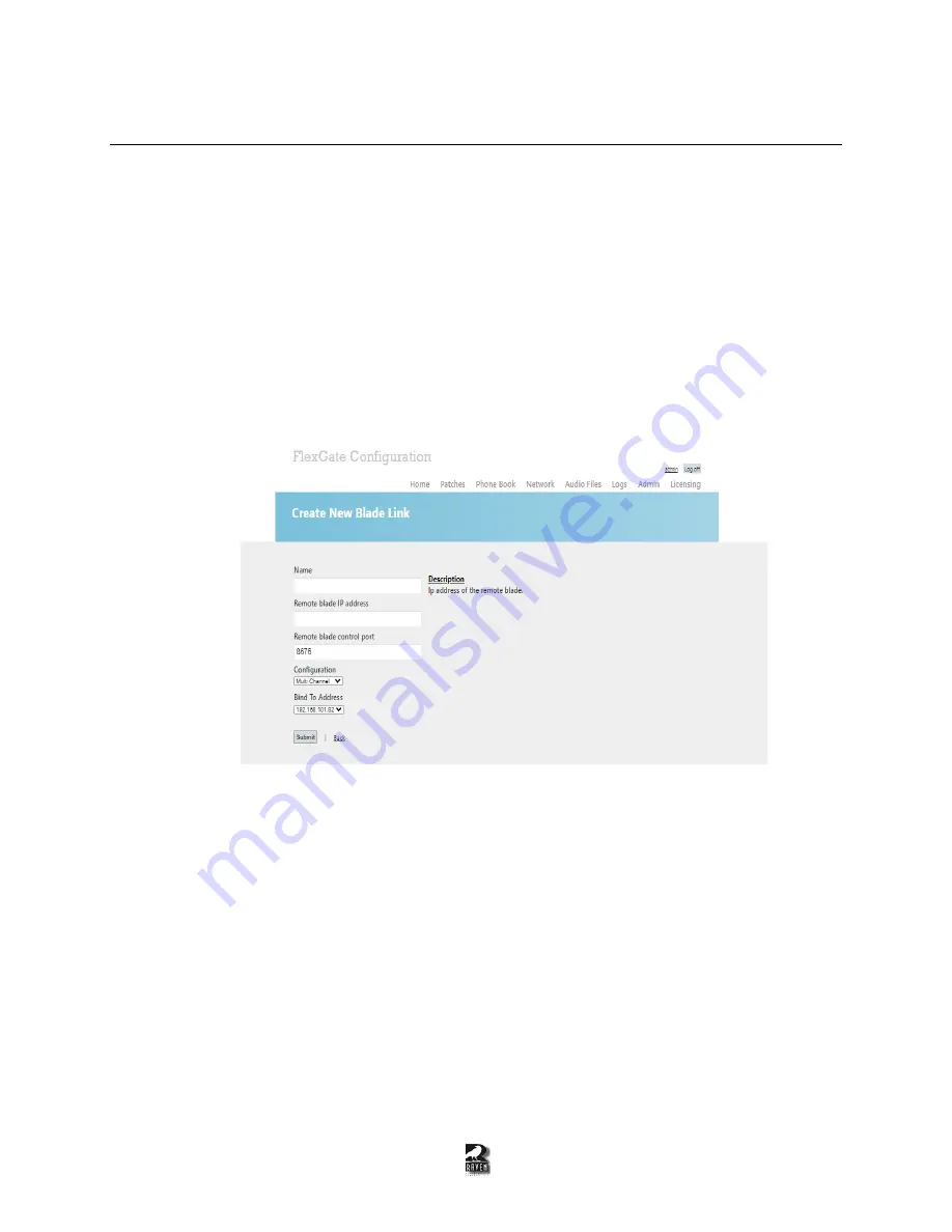
Click on the “Blade Link” section on the left side panel to create the new interface and will look 

like Figure 6-7. 


Figure 6-7: The FlexGate configuration page for Blade-Link.  


3.


Fill out the Blade-Link settings: 

Name: 

This will be the name of the Blade-Link that will show up under the endpoints listings. 


Remote blade IP address:

 The IP Address of the blade that has a VoIP module and the Pyra 

firmware  
 

Remote blade control port: 

The control port that will be associated with this blade-link. The 

same port number needs to match the remote blade

s port number.   

 
Configuration: 

Single Channel is for 2-port Mini Blades and Multi Channel is for 8-port Blades. 

 
Bind To Address: 

The FlexGate can have multiple IP addresses, so choose the IP address that is 

on the same network that can reach the remote Blade.  

Summary of Contents for 47800A-003-V

Page 1: ...Last Updated on February 10th 2022 REV1 PYRA RoIP VoIP Interface User Guide Copyright 2022 RAVEN ELECTRONICS CORPORATION 4655 Longley Lane 106 Reno Nevada 89502 ...

Page 2: ...e Link Using Pyra Firmware 14 6 2 How to Connect Blades with a FlexGate Using Blade Link 18 7 SIP Channel 20 7 1 How to Associate an Analog Channel with a SIP Account 20 8 Saving the Configuration 23 8 1 How to Save the Configuration of the VoIP Interface for Future Restores 23 9 Resetting the VoIP 24 9 1 How to Reset the VoIP to Have Default Settings through Hardware 24 9 2 How to Reset the VoIP ...

Page 3: ... Connecting to the VoIP Interface To configure a Blade that has a VoIP interface in it you will need the power supply sent with the unit as well as a CAT 5 ethernet cable that is connected to your network Figure 1 1 shows the front view of an 8 port Blade and Figure 1 2 shows the front view of a 2 port Mini Blade Figure 1 1 Front view of the 8 port Blade Figure 1 2 Front view of the 2 port Mini Bl...

Page 4: ...pter that is on your network and go to Properties Internet Protocol Version 4 TCP IPv4 Properties 5 Configure your network adapter with the following parameters Please take note of your current settings so that you can revert them after VoIP provisioning is finished IPv4 Address 192 168 50 100 Subnet mask 255 255 255 0 Default Gateway Leave Blank Preferred DNS server Leave Blank Secondary DNS serv...

Page 5: ...n 9 Figure 1 4 shows the System Information page that will be brought up once entering the correct username and password Figure 1 4 The System Information page that will pop up once correctly connecting to 192 168 50 65 and entering the correct credentials ...

Page 6: ... Type in the new username password and the password again to confirm Click the Save Changes button to apply the new credentials 3 If the username and password are changed a pop will appear looking like Figure 1 6 If the passwords do not match it will look like Figure 1 7 Figure 1 6 The popup that will appear confirming that the username and password was changed Figure 1 7 The popup that will appea...

Page 7: ...et to the Static IP so you can choose the IP address on your own If you want the DHCP to find an address for you choose Dynamic IP and click the Save Changes button Static IP Address Address The new IP Address desired for the VoIP interface Mask Subnet mask Default Router The main Router Gateway of your network DNS Primary The primary DNS server for you network if needed DNS Secondary The secondar...

Page 8: ...olarity This defines the PTT polarity This is defaulted to normally open when unactive and makes a switch closure when active Unchecking the box will reverse this COR Polarity This defines the COR input polarity This is defaulted to normally open when unactive and detects a switch closure when COR is inputted Unchecking the box will reverse this Dtmf Detect Makes it so the M4x channel can detect D...

Page 9: ...ire 4 wire Ports Refer to Figure 3 2 and Figure 3 3 for the pinouts for the 153 modules Note the E Lead is COR input and the M Lead is PTT output Figure 3 2 The RJ 45 connector for reference Figure 3 3 The pinout for the 153 modules ...

Page 10: ... panel and it will look like Figure 4 1 Figure 4 1 Conferences web interface 2 Type the name of the bridge being configured 3 Select the ports that need to be bridged as shown in Figure 4 2 Figure 4 2 Selecting the different ports to be added to the bridge 4 Click the Create 5 Check the Box labeled Enable 6 Create more bridges if needed ...

Page 11: ...nnel Setup page on the left side panel and it will look like Figure 5 1 Figure 5 1 Channel Setup web interface 2 Type the name of the RTP stream 3 Select RTP Channel under Channel Type and click Create 4 A pop up will appear labeled Account Configuration as seen in Figure 5 2 Fill out the RTP settings ...

Page 12: ... then be pointed towards a Multicast IP Address 224 0 0 0 to 239 255 255 255 Multicast TTL The Multicast Time To Live which is number of times the data can pass through a router If the TTL field reaches 0 before the destination the data is discarded Used only for Multicast Silence Suppression Trigger The Raven will only send audio packets on VOX if set to Enable If set to Disable packets will alwa...

Page 13: ... the RTP stream with a port 8 Click the name of the RTP channel and one of the ports that the RTP stream will be directed towards as shown in Figure 5 3 Figure 5 3 Selecting the RTP channel and one of the ports 9 Click the Create button and the conference will be shown 10 Click the Enable checkbox to enable the conference between the RTP stream and the port ...

Page 14: ...no Port number entered it will automatically be defaulted to Port 8676 Figure 6 1 Example of entering the non server IP address on the 3 Enter the IP Address Port of the non server Blade In our example the 8 port Blade is our dedicated Blade Link Server so we will enter 192 168 50 80 for the Mini Blade Do not go onto the non server Blade Setup webpage and enter the IP Address Port for the Dedicate...

Page 15: ...ve the option for Port 2 as seen in Figure 6 2 9 Click Save Changes 10 Navigate to Blade Setup on the non server webpage 11 Under Blade Link IP and Associated Port the server Blade will be populated Since it is an 8 port Blade there will be more options for the Ports as seen in Figure 6 3 In this example Port 1 was chosen Figure 6 3 The information of the server Blade will be populated and will ha...

Page 16: ...is shown in Figure 6 4 The Green LED on the Remote Blade indicates that it is properly linked and the unit is not down Figure 6 4 The Bladelink Status page showing the different Local Blades and Remote blades depending on which website you are looking at 14 Confirm when there is a COR input in the ports chosen in steps 8 and 11 there is a PTT on the opposite side Figures 6 5 and 6 6 shows Blade Li...

Page 17: ...1 on the sever Blade and PTT output on Port 2 on the non server Blade indicating Blade Link is working Figure 6 6 COR input on Port 2 on the non sever Blade and PTT output on Port 1 on the server Blade indicating Blade Link is working ...

Page 18: ... the RTP channel will determine where the blade link signaling will be directed towards 1 Navigate to the FlexGates webpage and log in 2 Click on the Blade Link section on the left side panel to create the new interface and will look like Figure 6 7 Figure 6 7 The FlexGate configuration page for Blade Link 3 Fill out the Blade Link settings Name This will be the name of the Blade Link that will sh...

Page 19: ...de link and clicking the enable button The RTP Channels does not correspond to the individual ports Do not skip unused channels since it can cause problems loading in the settings during FlexGate restarts If the checkbox for COR is not checked it will operate in VOX mode This is good for radios that do not provide the COR on the input side of the VoIP interface but do require a PTT for the output ...

Page 20: ...e 1234 It is assumed the EXT 1234 under the SIP server is already setup and is ready to connect to this blade The analog channel will be unable to initiate a SIP call but an external device connected to the same SIP server such as a SIP phone or Raven s IP Deskset can start a call 1 Navigate to the Channel Setup page on the left side panel and it will look like Figure 7 1 Figure 7 1 Channel Setup ...

Page 21: ... enabled disabled by the checkbox after it is created Proxy Settings Proxy username The EXT number that is associated with that endpoint under the SIP server Proxy password The password for this endpoint This should match the password setup under the SIP account Proxy address Not required if registering with the SIP Server domain Proxy port The port associated with the SIP server Placing a 0 in th...

Page 22: ...e of the SIP channel and one of the ports you want the SIP account associated with as shown in Figure 7 3 In this example we are associating Port 4 with the 1234 SIP account Figure 7 3 Selecting the SIP channel and one port that will be linked to the SIP EXT 9 Click the Create button and the conference will be shown 10 Click the Enable checkbox to enable the conference between the SIP channel and ...

Page 23: ...gure 8 1 Figure 8 1 Backup Restore web interface 2 Click the Download Settings button The settings will then be downloaded as a json file 3 To upload the json file to get the same configuration on a blade navigate to the same webpage 4 Click the Choose File button find the json that was downloaded saved and click the Restore Settings button The blade will perform a restart and will have the saved ...

Page 24: ... 9 1 Move the jumper to ERASE and MEM Some older modules were made without the jumper pins If you have one that does not have a jumper refer to Section 9 2 How to Reset the VoIP Interface to Have Default Settings through the Webpage to reset to default settings Figure 9 1 Location of reset jumper on VoIP module 4 Power cycle the blade by disconnecting it from power and reconnecting 5 After 10 15 s...

Page 25: ...store in the drop down 2 Click the Set Defaults button A pop up will appear asking if you want to reset to default settings as shown in Figure 9 2 Click the OK button to continue Figure 9 2 The pop up prompting you to confirm defaulting the VoIP interface settings 3 The blade will restart and will have the IP address of 192 168 50 65 once booted back up ...

Page 26: ...he name will appear to the right of the button 3 Click the Upgrade button A message will appear on the same webpage notifying it may take a couple of minutes It will look like Figure 10 2 Figure 10 2 The message that will be shown when the uploading process has begun 4 The page will be redirected to look like Figure 10 3 to inform the user the process of the update Once complete the username and p...

Page 27: ...re isn t two blades plugged in with the same IP address especially when configuring multiple new blades at once 11 2 Why Am I Getting E M Signaling One Direction but Not the Other Direction when Using Blade Link Step 1 Check to see if both ports are being pointed towards each other under Blade Setup when using Blade Link between two blades If using a FlexGate as the dedicated Blade Link server it ...

Page 28: ...lied the PYRA firmware to a blade that had different older firmware perform a reset to ensure the json file is properly formatted Step 2 If you applied an old json file from an older VoIP firmware to restore settings will cause a boot loop Perform a reset on the VoIP interface ...

Reviews: