Printed in China
07/09 8001025-01 Rev C
RavenSkyware
1315 Industrial Park Drive
Smithfield, NC 27577
Telephone:
+1-919-934-9711
Internet:
www.raven.co.uk
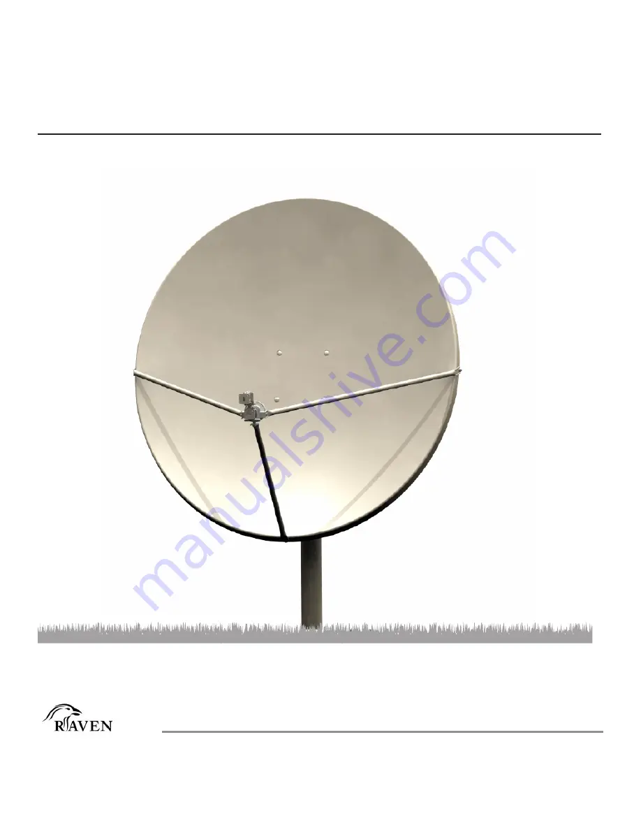
Assembly Instructions
Type 122 1.2 Meter Class I Antenna System
with Precision Az/El Cap Mount
8001025-01


