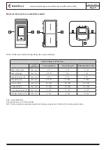
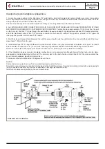
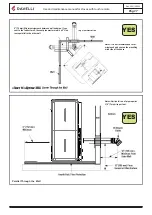
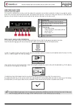
background image

Use and maintenance manual for stoves with touch remote

Pag.20 

Rev.0 05/12/2022

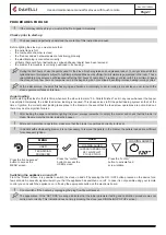
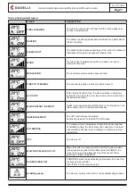
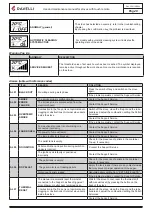
2- Icon indicating the status of the stove (see synthetic phase diagrams).

3- In the inactive phases (combined with the second part of the display) indicates the state of the stove. In the active phases, it 

indicates the operating power of the stove. In addition, by pressing the DOWN scroll button, you can display the power settings, that 

can be edited using the two scroll keys UP/DOWN: The confirmation of any change takes place automatically within 3 seconds from 

the change or by pressing the confirmation key. A sound signal indicates that the change has been confirmed.  


📌

After 5 minutes of inactivity, the remote control display dims to “SLEEP” mode while maintaining the radio connection to the 

stove. A subsequent press of the ON/OFF key reactivates the display.


📌

The first press of any key with active display turns on its backlight, not interpreting it as a command.

The display is subdivided into three parts:

1- It shows the current room temperature measured by the remote control. Moreover, if you press the DOWN scroll key you will 

display the temperature settings that can be changed using the two UP/DOWN keys. Any change made is confirmed automatically 

within 3 seconds from the change or by pressing the confirmation key. A sound signal indicates that the change has been confirme.

Time and date setting 

Below are given the steps for accessing the relative menu

User’s manual HANDHELD TOUCH RADIO

User’s manual HANDHELD TOUCH RADIO

Pag.20 

Pag.21 

Vers. 01 of:07.04.14

Vers. 01 of:07.04.14

2

3

1

2

3

1

FIRST INSTALLATION?

PRESS THE KEY RADIO 

ADJ ON THE STOVE

YES

MENU

USER

USER

SETTINGS

SETTINGS

DATE-TIME

USER

COMFORT CLIMA

MANUFACTURER 

ENGINEER

ENABLE EXT. TH.

CONTRAST

FW VERSION

ADJUST

LANGUAGE

SCREW FEEDING

CHRONOTHERMOSTAT

AIR-PELLET SET

STOVE STATE

Handheld touch radio initialization 

In order  to operate correctly, the handheld set should be interfaced with the electronic board installed inside the stove.  For this  

reason, on display appears the following message:  

If the handheld set is used for the first time, select 

YES

 using the selection keys and confirm with the dedicated key. 

On the display of the handheld set appears the following:  

Hold down for a few seconds the button of radio communication (RADIO ADJ) of the PCB, located on the back of the stove, to  

initialize the device.  

The flashing yellow LED indicates that the circuit board is waiting to receive the signal from the handheld set. 
By pressing the enter key on the handheld set, the components start communicating with each other. A check sign on the display,  

accompanied by a sound signal, shows that the initialization of the handheld set has been completed sucessfully 

.  

When you replace the batteries, you do not have to run the initialization procedure of the handheld set. In this case, when  

on display appears the message “FIRST INSTALLATION ?”, select 

NO

 and press the confirmation key.  

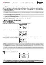
Description of the display 

The display of the handheld set is described below (in stand-by mode):  

After 5 minutes of inactivity, the display of the handheld set turns dark, switching to “SLEEP” mode, while maintaining the  

radio connection with the stove. By pressing the key ON/OFF, the display becomes active again. 

The first pressure of any key with the display active, lights up its backlight, but it is not, however 

considered a   command.  

The display is subdivided into three parts:  

1. It shows the current room temperature measured by the handheld set. Moreover, if you press the DOWN scroll key you will 

display 

the temperature settings that can be changed using the two UP/DOWN keys. Any change made is confirmed automatically 

within 3 seconds from the change or by pressing the confirmation key. A sound signal indicates that the change has been con

-

firmed. 

In the inactive phases (combined with the 3rd part of the display) indicates the state of the stove.  

In the active phases, it indicates the operating power of the stove. 

In addition, by pressing the DOWN scroll button, you can display the power settings, that can be edited using the two scroll  

keys        

UP/DOWN: The confirmation of any change takes place automatically within 3 seconds from the change or by pressing the con

-

firmation key. A sound signal indicates that the change has been confirmed.  

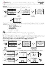
Time and date setting 

Below are given the steps for accessing the relative menu.  

Press the key  “access menu” to 

access  

the  

MENU page  

Press the key  

“confirm” to  

access the  

SETTINGS  

page  

Press the key  

“confirm”  

to access the  

USER page  

Press the key  “con

-

firm”  

to access the  page 

DATE-TIME  

Press the key “selection” for  

“selection”  

to switch to the second page  

of USER MENU and select  

SETTINGS.   

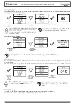
Press the increase key to change every single value 

Press the increase key to change every single value 

Press “confirm” to confirm the settings and switch to the next 

value. 

By pressing the key “back” for several times you will display 

the  stand-by page.  

MENU

USER

TECHNICIAN

PRODUCER

USER

LOADING AUGER

CHRONOTHERMOSTAT

SET AIR-PELLET

STOVE STATUS

USER

COMFORT CLIMA

SETTING

SETTING

DATE - HOUR

ENABLE T.EXT

CONTRAST

VERSION FW

ADJUST

LANGUAGE

Summary of Contents for Vittoria V

Page 1: ...USE AND MAINTENANCE MANUAL Stoves with Touch Remote Vittoria V Atena V RV 120 Touch...

Page 2: ...ns could result in property damage bodily injury or even death Contact local building or fire officials about restrictions and installation inspection requirements in your area Contact local authoriti...

Page 3: ...from combustible material 15 Standard horizontal installation configurations 16 CONTROLS AND USE 18 Control panel description 18 Radio touch remote control initialization 18 Description of the radio...

Page 4: ...the Technical service This stove must be used for the purpose for which it has been specifically manufactured Do not use the appliance as an incinerator or in any way other than that for which it was...

Page 5: ...erials and moved outdoors immediately If the ashes are disposed of by burial in soil or otherwise locally dispersed they should be retained in the closed container until all cinders have thoroughly co...

Page 6: ...e if cleaning is necessary GENERAL The Stove must only operate in rooms As it is controlled by an electronic board combustion is completely automatic and controlled and the control unit regulates the...

Page 7: ...not be used They must always be protected from the damp both during transport and in storage Do not place such fuel within the space heater installation clearances or within the space required for cha...

Page 8: ...blowtorch style with a high quality of incandescent pellets coming out of the grate Correct the pellet air set by reducing the percentage of air from 0 to 5 if not sufficient also increase the percen...

Page 9: ...0 Touch 0 6 79 25 2 19 2 8 Spare parts Use original spare parts only Do not use any substitute material Do not wait for the components to be worn before replacing them Replace a worn component before...

Page 10: ...1 8 5 3 Supply V Hz 120 60 120 60 120 60 Hopper capacity Lbs 50 50 50 Efficiency 79 25 79 25 79 25 Smoke temperature min max F 200 415 200 415 200 415 overll heating efficiency is determined using hi...

Page 11: ...loset or similar conceald space or a floor or ceiling Where passage through a wal or partition of combustible construction is desired the installationshall conform to CAN CSA B365 The stove must be in...

Page 12: ...rom any forced air intake of any other appliance G Minimum 2 clearance below eaves or overhangs H Minimum 1 clearance horizontally from combustible wall X Must be a minimum of 2 above the roof ridge T...

Page 13: ...9 0 4 0 3 5 2 2 0 3 9 8 8 2 7 8 7 9 5 6 3 1 8 7 5 3 2 8 3 5 8 0 1 0 7 8 3 4 7 8 9 4 5 3 7 M o d D E S C R I Z I O N E D a t a D i s A p p r M O D I F I C H E 5 4 0 0 0 0 0 0 0 1 M O D _ _ A 1 S C H E...

Page 14: ...P E R Q U O T E L I N E A R I A N G O L A R I S M U S S I E R A C C O R D I C L A S S E F I N E U N I E N 2 2 7 6 8 1 D O V E N O N I N D I C A T E 1 5 F C H P B e l o t t i v e n e r d 1 4 s e t t e...

Page 15: ...2 51 2 51 4 102 Back wall to pipe Inch mm 2 75 70 N A 1 25 Side wall to unit L R Inch mm 2 51 2 51 2 51 Side wall to pipe Inch mm 2 75 70 11 280 11 280 Front to unit A Inch mm 40 1000 40 1000 40 1000...

Page 16: ...stove with pipe attached towards the wall the pipe will go through the wall thimble Do not position the back of the stove closer than 2 51mm from the wall 4 Install listed type PL 45 degree elbow wit...

Page 17: ...pe If you vent to the furthest wall the vent pipe must maintain a 3 clea rance parallel to the other wall Top View Illustration Notes It is not recommended to ter minate exhaust vent on the prevailing...

Page 18: ...ges available in the menu Select the desired language with the scroll buttons and confirm your selection with the confirmation button In order to operate correctly the remote control should be interfa...

Page 19: ...tive cover of the battery on the back of the remote control as shown in Figure A and insert the 3 batteries mini pen style battery AAA 1 5V in the housing of the remote control and observe the poles I...

Page 20: ...FW VERSION ADJUST LANGUAGE SCREW FEEDING CHRONOTHERMOSTAT AIR PELLET SET STOVE STATE The display is subdivided into three parts 1 It shows the current room temperature measured by the handheld set Mo...

Page 21: ...LIMA DELTA COMFORT CLIMA DELTA RESTART DELTA SHUTDOWN DELAY SETTINGS SCREW FEEDING CHRONOTHERMOSTAT AIR PELLET SET STOVE STATE CONNECT AN EXTERNAL THERMOSTAT WITH A SIMPLE DRY CONTACT THEREFORE NOT PO...

Page 22: ...dry contact therefore not powered moreover we recommend you use a thermostat with a minimum offset of 3 C if you ntend to use the comfort clima function Description of menu functions Press the key to...

Page 23: ...om temperature If the type of system designed requires controlling the 3 way valve diagram 1 and 3 it is necessary to purchase the optional kit from the retailer or the authorized Ravelli dealer CHRON...

Page 24: ...RE OVER WE RECOMMEND YOU USE A THERMOSTAT WITH A MINIMUM OFFSET OF 3 C IF YOU INTEND TO USE THE COMFORT CLIMA FUNCTION Operating phases of the appliance Modulation During the work phase the appliance...

Page 25: ...W VERSION FW VERSION LANGUAGE LANGUAGE LANGUAGE LANGUAGE ADJUST ADJUST ADJUST ADJUST In Home mode instead of room temperature measured and settable appears the line T ON if the room in which the therm...

Page 26: ...ey you will confirm of data and switch to the page within SETTINGS menu The stoves equipped with ventilation system can heat the area in which are installed through the heat generated by the window an...

Page 27: ...mperature set is reached see the dedicated section WAITING START RESTART Switch on is requested but with the stove in cooling phase once this condition is met it restarts automatically IGNITION RESTAR...

Page 28: ...sists contact the Support Service AL 04 FAN BROKEN Fume exhaust encoder is not working or is connected incorrectly Contact the Support Service No power to fume extractor Contact the Support Service Th...

Page 29: ...tion to power the gear motor Check the mains voltage AL 15 AUGER TRIAC An internal part of the electronic board that controls the pellet auger is faulty Check the flue is free and clean Possible volta...

Page 30: ...THERMAL BREAKER below shows the location where to operate to reset the thermal switch with manual reset 1 By pressing the button OK on the display the alarm can be reset 2 Unscrew the protection cap a...

Page 31: ...r M3 Flue gas fan M4 Front room fan M5 Rear right room fan only for ducted stoves M6 Rear left room fan only for ducted stoves R1 Igniter S1 Flame probe S2 External thermostat S3 Room probe opt G2 Enc...

Page 32: ...600 a material based on vermiculite the result of research and development by Ravelli The main features of FIREX 600 are resistant to heat its lightness and excellent insulating capacities im proving...

Page 33: ...the Majolica cladding the aesthetic parts any damages caused by unsuitable installation and or use of the product and or shortcomings on the part of the customer The use of poor quality pellet or any...

Page 34: ......

Page 35: ......
Page 36: ...any variations to the features of its products and to the present manual without notice Aico S p A Headquarter Via Consorzio Agrario 3 25032 Chiari BS Italy Research and Development Centre Viale del c...

Reviews: