background image

30 

Page 8

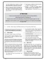
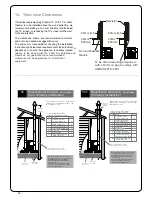
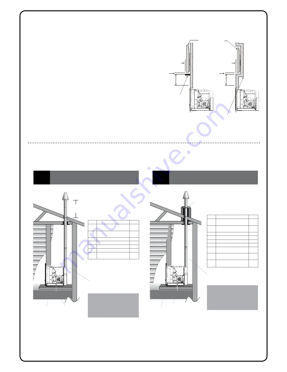
13.  Television Clearances

If electrical equipment (eg Plasma TV, LCD TV or home 

theatre) is to be installed above the wood pellet fi re, we 

recommend installing a non combustible mantle below

the TV screen, or recessing the TV screen into the wall,

for heat protection.  
The clearances shown are recommended minimums, 

and are to be treated as suggestions only.  
The end user is responsible for checking the installation 

instructions and clearance requirements of their electrical 

appliances to ensure the appliance is suitably located

equipment.


r

o

f  

ll

a  

l

a

c

ir

t

c

e

l

e


appropriate

  ll

i

w  e

b  

a

clear nces

recommended

il

l

e

v

a

R


o

d  t

o

n  

e

e

t

n

a

r

a

u

g

  e

s

e

h

t


n

o

it

a

l

e

r


o

t  e

h

t   d

o

o

w

  t

e

ll

e

p

  .

e

ri

f

  t

e

ll

e

P

 ri

F e 

s

n

o

it

u

l

o

S

 d

n

a  

n

i  

50mm (min)

40mm
330mm

Non combustible
Mantle

To be zero rated using eterpan etc
with a 12mm air gap to comply with
AS/NZS 2918 : 2001

Television

50mm (min)

40mm
330mm

Each 55 Built-in-Heater Flue Kit 

(non-Chimney installation) contains:-

This flue kit may be used in new or existing 

timber

chimneys

.  The overall height of the flue is 3.6m.

Kit is supplied in a carton.

Note:

The Davin 55 Built-in-Heater Flue Kit

(non-Chimney) complies with AS/NZS

2918:2001 as per Applied Research Test

Report 05/1185, dated 15 September 2005. 
All fires must be installed by a qualified

installer as per the manufacturer’s

instructions and AS/NZS2918:2001.

600mm from

roof

penetration

110mm minimum
clearance if lined 

150mm

(minimum)

Part No.

Description

Quantity

1

Galvanised outer liner

Ø100mm x 900mm long

4

2

Stainless steel inner liner

Ø75mm x 900mm long

4

5

Inner/outer flue liner spacer

4

8

Rain cap 75mm

1

9

Rain cap 100mm

1

702

Support Angle 950mm Long

2

55

avelli

Sara & 

Camino

-

Ravelli

new

  a

r

a

S


o

i

n

i

m

a

C


home

(non-Chimney installation)

Each 54:1 Built-in-Heater Flue Kit 

(Chimney installation) contains:-

This flue kit may be used in new or existing 

timber

chimneys

.  The overall height of the flue is 3.6m.

Kit is supplied in a carton.

Note:

The Davin 54:1 Built-in-Heater Flue Kit

(Chimney) complies with AS/NZS

2918:2001 as per Applied Research Test

Report 05/1185, dated 15 September 2005. 
All fires must be installed by a qualified

installer as per the manufacturer’s

instructions and AS/NZS2918:2001.

Part No.

Description

Quantity

1

Galvanised outer liner

Ø100mm x 900mm long

4

2

Stainless steel inner liner

Ø75mm x 900mm long

4

5

Inner/outer flue liner spacer

2

8

Rain cap 75mm

1

9

Rain cap 100mm

1

10

Telescopic offset 75mm (Stainless)

(2 x 45° bends)

2

11

Telescopic offset 100mm (Galvanised)

(2 x 45° bends)

2

702

Support Angle 950mm Long

2

R a v e

Ravelli

 Sara 


& Camino - new 

(Chimney installation)


home

Heat-resistant

Seismic restraint

Chimney to

by builder

150mm 

(minimum)


NOTE: Camino must be installed on an approved, raised-stand, while Sara can be installed lower to the 

 oor with an 

optional 45mm base.


55:1


Each 55 Built-in-Heater Flue Kit 
(non-Chimney installation) contains:-

y

t

i

t

n

a

u

Q

n

o

i

t

p

i

r

c

s

e

D

o

N


t

r

a

P

1

Galvanised outer liner
ø100mm x 900mm long

4

2

Stainless steel inner liner
ø75mm x 900mm long

4

5

Inner/outer flue liner spacer

2

8

Rain cap 75mm

1

9

Rain cap 100mm

1

This flue kit may be used in new or existing timber

chimneys.  The overall  height  of  the  flue  is  3.6m.

Kit is supplied in a carton. 

Heat-resistant

floor protector

Seismic restraint

(to be fitted)

600mm from

roof

penetration

Ravelli Sara & Camino 

- new home

(non-Chimney installation)

55

25mm minimum clearance if lined:

75mm minimum clearance if unlined

Note: The Davin 55 Built-in-Heater Flue Kit 
for Sara and Camino (non-Chimney) complies 
with AS/NZS2918:2001 as per Applied 
Research Test Report 05/1185, dated 15 
September 2005.
All fires must be installed by a qualified 
installer as per the manufacturer’s instruc-
tions and AS/NZS2918:2001.

6c     Ceiling thimble ø107mm hole         1          

702 Support angle 950mm long

– 40mm x 40mm sides

2

46 

Velocity cone

1

Each 55:1 Built-in-Heater Flue Kit 
(Chimney installation) contains:-

y

t

i

t

n

a

u

Q

n

o

i

t

p

i

r

c

s

e

D

o

N


t

r

a

P

Galvanised outer liner
ø100mm x 900mm long

4

Stainless steel inner liner
ø75mm x 900mm long

4

5

Inner/outer flue liner spacer

2

8

Rain cap 75mm

1

9

Rain cap 100mm

1

11 

Telescopic offset 100mm 
(Galvanised) - (2 x 45° bends)

10 

Telescopic offset 75mm 
(Stainless) - (2 x 45° bends)

Ravelli Sara & Camino 

- new home

(Chimney installation)

55:1

This flue kit may be used in new or existing timber 

chimneys.  The overall  height  of  the  flue  is  3.6m. 

Kit is supplied in a carton. 

Note: The Davin 55:1 Built-in-Heater Flue Kit 
for Sara and Camino (chimney) complies 
with AS/NZS 2918:2001 as per Applied 
Research Test Report 05/1185, dated 15 
September 2005. 
All fires must be installed by a qualified 
installer as per the manufacturer’s 
instructions and AS/NZS2918:2001.

Heat-resistant

floor protector

Chimney to

be flashed

by builder

25mm minimum clearance if lined:

75mm minimum clearance if unlined

Seismic restraint

(to be fitted)

1

1

6         C

   eiling Thimble    1 07mm h

  ole  

1

ø

702 Support angle 950mm long

– 40mm x 40mm sides

2

46 

Velocity cone

1

1

2

Summary of Contents for Camino

Page 1: ...tion Manual Fire Owner s PLEASE READ THIS ENTIRE MANUAL BEFORE INSTALLATION AND USE OF THIS WOOD PELLET FIRE FAILURE TO FOLLOW THESE INSTRUCTIONS COULD RESULT IN PROPERTY DAMAGE BODILY INJURY OR EVEN DEATH Contact your local building or about restrictions and installation inspection requirements in your area ...

Page 2: ...hnical requires fire and individualised air pressure adjustments to ensure it will operate safely and ef ciently and to avoid possible damage to the re or the home Installation of the Camino Wood Pellet re by a non registered installer will void the warranty and may result in your local authority refusing to approve the ry necessa permits If you require a registered Pellet Solutions Fire installer...

Page 3: ...utions 8 Setting up your pellet 8 Menu Descriptions 8 Menu One Setting the Clock 8 Menu Two Set Crono Programmable Thermostat 9 MenuThree SelectLanguage SettingtheLanguage 10 Menu Four View Settings 10 Menu Five Stove State Fire Status 10 Menu Six Working Hours 11 Description of Screen Displays 11 Troubleshooting 11 Explanation of Alarms 12 Maintenance and Cleaning 13 Burn Pot Liner daily 13 Heat ...

Page 4: ...whereas Please read this entire manual before operating your Ravelli Wood Pellet Fire Failure to follow these instructions may result in poor performance damage to of replacement parts not supplied by the manufacturer is prohibited All national and local regulations shall be complied with when installing this appliance Your local Pellet Solutions e r i F dealer will be happy to assist you in obtai...

Page 5: ... use 2 3 each lighting You must check that the Burn Pot Liner where the combustion takes place is clean and that no waste or residue blocks the holes in order to always guarantee excellent combustion of the stove This will help avoid possible overheating which could causes changes in the colour of the paint as well as failure to light the stove deposits may be formed which have to be immediately b...

Page 6: ...n is by means of the resistance 2 which overheats the air from the special intake 5 which on contact with the pellets will allow the exhaust smoke is deviated towards the stainless steel exchanger 6 and through the smoke extraction tube 4 it is released into h t i w e h t e k o m s t s u a h x e t e l t u o 9 connection e u l f h g u o r h t e h t e h t 2 3 6 8 5 4 9 1 7 10 1 pellet feeding auger ...

Page 7: ...oor maintenance Failure to observe the instructions in the manual Use not compliant with the safety instructions Installation that is not compliant with the regulations in force in the country Installation by personnel who are not or authorized and repairs that are not authorized by the manufacturer Use of spare parts that are not original Exceptional events 4 5 Spare Parts To avoid voiding your w...

Page 8: ...our remote control ROOM TEMPERATURE SETTING see 6 3 1 on page 9 5 2 Filling the Pellet Hopper Check hopper for foreign objects then empty the bag of pellets into the hopper DO NOT OVER FILL as miscellaneous pellets could smoke if left to rest on an operating heater Store pellets at least one metre 1m away from the can be pulled out on a runner system so the hopper maintenance How to extract the st...

Page 9: ...ouses may work better on other settings 6 Switch the power to the fire back on the fire must be pushed back into its cradle when this is done 7 Press the red button quickly after tuning the power on 8 If the operation is successful UNIT LOADED 0 1 2 or 3 will appear on the handset You may now need to turn the power to the fire off and back on again to refresh the connection with the remote 5 5 Swi...

Page 10: ...on the display and the current time will be shown Change the hours of the Display Meaning 01 Monday 02 Tuesday 03 Wednesday 04 Thursday 05 Friday 06 Saturday 07 Sunday OFF Deactivated 5 6 Operating Instructions The heater is completely automated and will self regulate off phase guaranteeing safe functioning The burn pot used for combustion allows most of the ashes produced by the combustion of the...

Page 11: ...etting a thermostat built in which measures the ambient temperature The room temperature will be shown on the display For the thermostat to control the pellet place in the room where it can measure the typical room temperature P 3 PROG 1 POWER If this black line is not lit up the timer function will not be active To activate set the day and time See 6 2 Menu One Setting the Clock on page 8 Descrip...

Page 12: ... This menu is used when a Service Technician has to understand the parameters set in the machine to find any modifications to improve the functioning of the stove 6 6 Menu Five Stove State Fire Status In this menu you can check the correct functioning of some of the key components of the pellet fire To enter this menu either 1 Press Button 7 Menu 01 Set Clock will appear 2 Then press and hold 6 fo...

Page 13: ...LING WAITING FOR START The stove is cooling DOWN When stove has cooled down it will start automatically ON WAITING FOR RESTART The switch ON phase when the stove is warm started The operation is same as phase ON HOT SMOKE The max temperature of smokes is reached to reduce temperature feeding pellets and air draft reduce at POWER 01 OFF The stove is off 6 8 Description of Screen Displays 7 Troubles...

Page 14: ...city supply to smoke extractor Contact local Service Technician The smoke extractor is blocked Contact local Service Technician DEPRESSION ALARM The combustion chamber is dirty Follow the cleaning operations of the stove as per the instructions manual The flue is blocked Check that the flue is clear and clean The vacuum switch is malfunctioning Contact local Service Technician THERMAL ALARM WITH R...

Page 15: ...Seals Gaskets Owner Technician Pellet Hopper Owner Technician Fresh Air Intake Owner Technician Blower Mechanisms Technician Fire exhaust passages Technician Flue system Technician Frequency recommendations given are based on typical generally over the summer or at the start of the season The purpose of this maintenance is to make sure that the heating season We recommend you draw up an annual con...

Page 16: ...of doing this is to vacuum it out Make sure the air intake is clear of ash or debris this can also be vacuumed out to ensure it is clean Place the burn pot back into the fire making sure that the burn pot is located correctly The Flame Trap located in the top of the burn chamber below the heat exchanger tubes should be removed and the ash which has been scraped off the heat exchanger tubes cleaned...

Page 17: ...ina will form after a few hours A poorly performing fire will get brown or black deposits on the glass The glass must be cleaned only when the fire is cold using a damp cloth or kitchen paper Sometimes it is best to dirty the cloth slightly with ash from the fire itself to create a slightly abrasive action which will help to remove stubborn deposits The door glass is made of special high temperatu...

Page 18: ...ded electrical protection It is very important that the be thoroughly cleaned and serviced as stated above Exposed metal part may be painted with high temperate paint to prevent rusting over the off season 8 12 Cleaning the surfaces To clean the surfaces on the painted metal parts use a damp cloth Important the use of aggressive detergents or abrasive cleaners can damage the surfaces of the stove ...

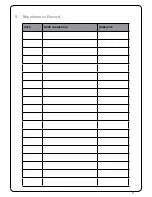
Page 19: ...17 Page 16 9 Maintenance Record DATE WORK CARRIED OUT SIGNATURE ...

Page 20: ...itional service fees may apply if you are seeking warranty service from a dealer other than the dealer from whom you originally purchased the product Check with your dealer in advance for any costs to you when arranging a warranty call Travel and shipping charges for parts are not covered by this warranty 10 2 Warranty Period Warranty coverage begins at the date of installation In the case of new ...

Page 21: ...e electrical power supply to the pellet Non Pellet Solutions Fire approved venting components hearth components or other accessories used in conjunction with the appliance Any part of a pre existing system Pellet s Ravelli Solutions Fire obligation under this warranty does not extend to the pellet capability to heat the desired space Information is provided to assist the consumer and the dealer in...

Page 22: ...20 Page 19 11 Proof of Purchase Warranty Date of Purchase Amount Paid Payment Method o Credit Card o EFTPOS o Cash o Other Attach receipt and other documents here ...

Page 23: ... Architectural Drawings 27 Example of Cavity Design Section View 27 Example of Cavity Design Top View 28 Adjusting the Support Frame 29 Seismic Restraint 29 Fixing to Concrete Floor 29 Fixing to Timber Flooring only 29 Fixing to Timber Floor Framing 29 Ventilation 29 Television Clearances 30 Flueing 30 Flashing Options 31 Controls and Menus 31 Description of Controls 31 Turning the Unit On 31 Menu...

Page 24: ...nt access this should be sufficient 5 Check there is sufficient ventilation for combustion air and this is unaffected by mechanical extraction An external air intake may be required see 5 Creating the Cavity on page 26 for cavity ventilation requirements 6 There must be sufficient circulation of air in the room where the pellet fire is installed Never open the door of the pellet fire while it is functi...

Page 25: ...the appliance has been installed In the event of failure to respect these precautions Solutions ire F t e l l e P declines all responsibility 1 The fire must be installed on a floor with sufficient carrying capacity If the existing building does not meet this requirement appropriate measures must be taken i e a load distribution plate 2 Camino must be installed on a non combustible surface This surfa...

Page 26: ...es such as high salt content Wood pellets manufactured to the AS NZS 4014 6 standard are recommended Dirty fuel will adversely affect the operation and performance of the unit and will void the warranty The Pellet Fuel Industries PFI has established standards for wood pellet manufacturers We recommend the use of pellets that meet or exceed these standards Ask your dealer for a recommended pellet t...

Page 27: ...al Use not compliant with the safety instructions Installation that is not compliant with the manual and regulations in force in the country Installation by personnel who are not qualified or authorised Modifications and repairs that are not authorized by the manufacturer Use of spare parts that are not original Exceptional events If you require further information please contact your Pellet Solutio...

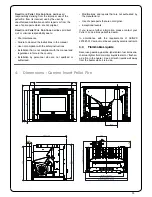
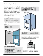
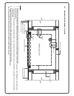
Page 28: ... of support stand Internal Cavity Dimensions A Width m m 0 6 1 1 n i m B Depth m m 0 5 7 m o r f t n o r f f o l l a w t h g i e H C 2150 Includes 110mm clearance from rear of flue spigot box Dependendent on height at which the support frame is set WALL WALL WALL WALL WALL WALL WALL WALL L N K M Additional Clearances to Combustibles K from exhaust spigot to cavity wall 110mm L from side of re to ca...

Page 29: ...ure 3 Comply with all minimum distance to all combustible surfaces Any modifications to the dimensions shown to be verified by consultation with the relevant Building Consent Authority 4 Ensure there is a minimum of 100cm2 ventilation into the cavity this does not need to be from the outside 5 Installers must ensure adequate vermin proof measures are incorporated into the cavity construction if appl...

Page 30: ...ont of the enclosure 3 Comply with all minimum distance to all combustible surfaces Any modifi cations to the dimensions shown to be verifi ed by consultation with the relevant Building Consent Authority 4 Ensure there is a minimum of 100cm 2 ventilation into the cavity this does not need to be from the outside 5 Installers must ensure adequate vermin proof measures are incorporated into the cavity ...

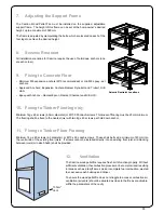
Page 31: ... 90 coach screws Thickness of flooring must be 20mm minimum The flooring shall be fixed to the nearest joist with two 8g x 40 screws per hold down anchor 11 Fixing to Timber Floor Framing Minimum 14g x 60 screws 6 3 diameter or M10 x 90 coach screws These shall be fixed a minimum of 40mm into the centre line of the existing floor joists If screws cannot be installed directly into an existing floor joist...

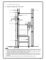
Page 32: ...r flue liner spacer 2 8 Rain cap 75mm 1 9 Rain cap 100mm 1 10 Telescopic offset 75mm Stainless 2 x 45 bends 2 11 Telescopic offset 100mm Galvanised 2 x 45 bends 2 702 Support Angle 950mm Long 2 R a v e Ravelli Sara Camino new Chimney installation home Heat resistant Seismic restraint Chimney to by builder 150mm minimum NOTE Camino must be installed on an approved raised stand while Sara can be ins...

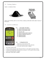
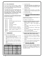
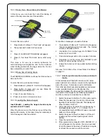
Page 33: ...ting Power P6 Multifunction Button P7 Multifunction Button 16 2 Turning the Unit On 1 Ensure burn pot is clean and free of ash 2 Slide the heat exchange cleaner in and out three times 3 To turn unit on hold down button 3 ON OFF 4 Control Screen will show START 5 To change the Power setting first press P5 then use buttons P1 or P2 to adjust the heat output of the fire 6 To change the Thermostat Setti...

Page 34: ...firm 7 TIME CLOCK will appear on the display and the current time will be shown Change the hours of the day with 1 or 2 24 hour clock example 4 30p m would be 16 30 8 Press 7 to confirm 9 MINUTES CLOCK will appear on the display Change the minutes of the day with buttons 1 or 2 10 Press 7 to confirm 11 Press 3 to exit the menu 16 3 2 Menu Three Select Language Setting the Language Some fires may be in...

Page 35: ... for a couple of minutes 4 Remember to turn the screw OFF SCREW 0 with button 2 before exiting button 3 5 Empty the burner pot of any pellets before starting the fire Also see 16 3 4 Menu Five Stove State Fire Status on page 33 16 3 7 How to synchronise the remote control with the fire All insert stoves are fitted with remote control radio wave handset and a receiver located on the right hand side of...

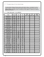
Page 36: ...ew power 1 PR06 Sec 7 1 Screw power 2 PR07 Sec 2 1 Screw power 3 PR08 Sec 5 2 Screw power 4 PR09 Sec 3 2 Screw power 5 PR10 Sec 9 3 Re start threshold PR11 C 80 No pellet threshold PR12 C 50 Off threshold PR13 C 45 Maximum threshold PR14 C 250 Fan threshold PR15 C 80 Smoke ignition PR16 RPM 2100 Ignition smoke speed PR17 RPM 1950 1 smoke speed PR18 RPM 1250 2 smoke speed PR19 RPM 1450 3 smoke spee...

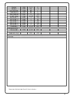
Page 37: ...120 Comfort climate PR42 on off OFF Fan 2 speed 1 PR43 V 125 Fan 2 speed 2 PR44 V 140 Fan 2 speed 3 PR45 V 160 Fan 2 speed 4 PR46 V 180 Fan 2 speed 5 PR47 V 210 Draft setting PR48 on off OFF or for version Air 03 Screw encoder PR49 on off OFF Magnehelic on high WG 0 0 1 Comments Please reference future for sheet parameter this keep ...

Page 38: ...ow Green Yellow Green Yellow Green 7 8 11 12 9 10 3 4 Brown Brown Yellow Green Brown 10 9 Brown Blue Yellow Green Black Blue Blue Brown 1 6 6 5 5 6A 5A 1 2 2 6 Encoder Red Black White Black Brown White 7 8 Ambiant temperature sensor NOT SUPPLIED Clock Motherboard Cod I023 9 Flat cable 3 4 Black Black Microswitch 7 SERIAL White Black Red TERRA Switch Rear view ...

Page 39: ...peration of my Pellet Fire I understand that warranty conditions require an authorised Pellet Fire Solutions Installer to complete the installation Signed Date Installation Details Pellet Fire Model Serial Number Installation Date Freestanding Flue Kit Internal External Standard Fireplace Insert Flue Kit Insert BIH Installer Details Installers Name Phone Number Passed Inspection Yes No if no why D...

Reviews: