GB
Pic. 5
7
8
21
13
16
14
12
÷ 52
9
Pic. 4
55
13
÷
13
12
21
16
14
7
Bathtub rim
Pic. 3
30
3÷2
3
22
2
5
Bathtub rim
Panel
3
2
9
6
7
3
17
4
8
45
567
-
565
Bathtub support
Panel
Pic. 2
567
-
565
30
3÷2
3
2
20
5
Bathtub rim
3
Pic. 1
565
35
12÷15
A
Front panel
CONTENTS OF PANELKIT
3 pcs
11
s
1
3
s
3
s
4
s
3
s
4
s
2
s
2
s
2
s
2
s
1
1
2
s
3
s
pc
pc
pc
pc
pc
pc
pc
pc
pc
pc
pc
pc
pc
pc
pc
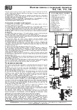
Mounting the Supports
Mounting the Panel
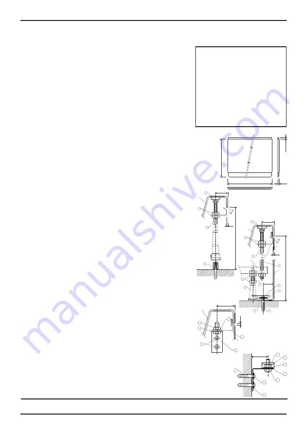
It is possible to use plastic panels of given lengths and widths for all sizes of the VANDA,
CAMPANULA, FRESIA, and SONATA rectangular bathtubs. The panel can be fastened to the
bathtub using the parts included in the PANELKIT.
Depending on the way the bathtub is installed in the bathroom, it is possible to use a single front
panel ( in a recessed area), a front and a side panel (in a corner), or a front and two side panels
(against a wall).
WE RECOMMEND THAT THE BATHTUB WITH PANEL BE MOUNTED INTO
A COMPLETELY FINISHED AND TILED BATHROOM WITH PREPARED PLUMBING
1.
2.
3.
picture 2
(position 22 in picture 3)
(position 5)
4.
5.
6.
7.
8.
9.
10.
11.
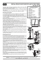
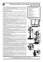
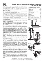
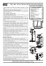
Turn the bathtub upside down, and place the cardboard and styrofoam packaging on the
corners of the tub so that the rim of the tub and the raised headrest will not be damaged.
On one side of the metal supports there are two 12.5mm diameter holes drilled closely to each
other. This end of the support is always mounted on the side where the front panel will be.
As illustrated in
, screw the 570mm rods into the outer holes, and on the upper end
mount a panel clip between two nuts
. Fit the end of the rod with
a plastic shoe
.
Screw the bolts with plastic legs into the other 12.5mm diameter holes. Depending on the
bathtub type, use 2 or 3 legs for each support.
Place the completed support structure over the bottom of the tub, at a right angle to the
lengthwise axis of the tub, according to the distances given in the mounting instructions for your
type of tub. Mark the position of the supports on the bottom of the tub.
Move the support so that the center of the hole for the long threaded rod is 30mm from the outer
edge of the bathtub (on the panel side), and so that the clip is 2 - 3 mm from the edge of the tub.
Check the position and mark the position of the mounting holes onto the tub. Remove the
supports and drill the holes with the drill bit from the assembly kit. ATTENTION! Only drill into the
reinforced part of the bottom of the bathtub! When drilling, use a stop set at 10mm so that you do
not damage the acrylic on the inside of the tub.
Place the support structure back over the tub and fasten with 5.5 x 16mm screws.
Place the threaded rod with clip into position over the bathtub and copy the position of the plastic
shoe onto the tub. Glue the plastic shoe in place with a fast drying glue. When it has set, gently
tighten the nut of the support so as not to deform the upper rim of the bathtub. Use silicone to
secure the perimeter of the shoe to the tub.
Set the clip to the proper height about 3mm from the upper edge and about 2-3mm from the outer
edge of the bathtub.
Turn the tub over and place it into its final position. Adjust the tub using a level. ATTENTION! If
using a panel, measure the distance from the floor to the rim of the bathtub. It should be
565 - 567mm.
Outline the upper border of the bathtub on the wall and arrange the brackets according to the
mounting instructions for the bathtub. Screw the brackets to the dowels placed 55mm below the
marked edge of the tub on the wall.
12.
13.
(position 6 in picture 3)
14.
(picture 3, pos. 22)
15.
(position 20)
16.
pictures 4 and 5
(picture 5, pos. 21)
(pic. 5, pos. 14)
17.
18.
19.
picture 2
20.
21.
22.
Slide the panel into the clips and align it. Draw the outline of the panel on the floor. In the same
way, mark the position of the upper part of the panel on the side walls. Lay the panel aside.
On the floor, arrange the 3 plastic parts designed as stops
. Measure
45mm from the marked outline, drill an 8mm hole, insert a dowel and bolt the bottom stops.
According to picture 2, assemble the additional leg with the 570mm threaded rod and spring
clip
. Place it in the center of the long side of the tub and lightly press it under
the rim of the tub, 30mm from the outer edge. Adjust the support to a vertical position and mark the
outline of the leg onto the floor. Remove the support by loosening the plastic shoe.
Mark the center for the hole, and drill an 8mm hole into the floor for a dowel. Bolt the cylinder to
the floor
. During the final mounting of the tub, the plastic shoe will be held in place by
the cylinder.
When attaching the panel to the side walls, proceed according to
. With an M8
screw, attach the spring clip
to the angled plate
. Vertically
attach it to the wall so that the clip is about 3mm inside from the edge of the tub, and so that there is
a 3mm space between the outer edge of the tub and the angled side of the clip. Mark the outline of
the holes on the wall.
In the center of the ovals drill 8mm holes for the dowels and attach the square to the wall with
4x40mm bolts. Adjust the exact height and depth of the clip.
Now the bathtub may finally be installed. Apply an adequate amount of putty to the teeth of the
plastic brackets on the wall and set the bathtub on them. Again, check the placement of the panel,
tighten the nuts on the spring clips and on the legs.
Place the middle plastic shoe onto the cylinder on the floor. Apply quick glue to the upper part of
the plastic support and by rotating the legs, expand the support. Adjust it according to
.
Secure the position by applying putty around the plastic support.
Connect the siphon and finish all work under the bathtub. If there is a protecting foil on the
panel, remove it.
Apply putty to the teeth of the plastic brackets, and at a 45 degree angle slide the front panel
between the upper border of the bathtub and the brackets. Tilt the panel vertically and press it into
the stops on the floor. Adjust it. While the putty is hardening, the panel can be held in position with
an appropriate support.
If necessary, it is possible to putty the space between the panel and the wall, or the floor.
INSTALLATION OF BATHTUB WITH PLASTIC FRONT PANEL
150,160,170,180
2. Threaded rod M12x570mm
3. Nut M12
4. Plastic leg M12
5. Ringed shoe
6. Plastic bracket for tub
7. Bolt for dowel
4x40mm
8. Washer 5mm diameter
9. Dowel
8mm
12. Screw M8x16mm
13. Washer M8
14. Panel holder #8 - support
16. Washer 8mm diameter
18. Quick glue
20. Plastic cylinder 16mm diameter
21. Panel bracket #9 - spring clip
22. Panel bracket #10 - spring clip
∅
∅
RAVAK a.s., Obecnická 285, 261 01 Pøíbram, ÈR tel.: +420 318 427 111, fax:+420 318 427 269
e-mail: [email protected], www.ravak.com


