Ravaglioli YUCON T700 Technical Manual Download Page 44

The correct level of the pump oil is at approximately half of the
graduated scale on the pump oil level sight.

The total amount of oil to insert is approximately 370 ml.

10. Tighten the oil filler cap.

11. Make sure there are not any leaks from the side of the drain cap or from the filter.

12. Remount the side panel.

13. Connect the equipment from the mains.

14. Turn on the equipment.

15. Select: ADDITIONAL FUNCTIONS > TOTAL AND RESETTABLE COUNTERS

16. Locate the item: PUMP TIME

17. Press: RESET

17.3 Replacing the Paper in the Printer

Follow the instructions provided in the chapter 

Replacing the Paper in the Printer.

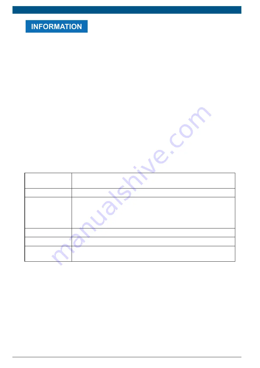
17.4 Periodical Checks

In order to guarantee a correct operation of the device we recommend you check the parts
that are the most subject to wear on a regular basis.

Parts subject to
wear

Check

Service hoses

Make sure there are no cuts, scratches or bulges.

Quick fittings

Make sure there are no signs of wear and that the hoses do not harden
during use.

Make sure the service hoses are connected properly.

Make sure there are no cuts or scratches on the O-rings.

Oil and UV bottles

Make sure they are clear and not damaged.

Wheels

Make sure the brakes are working properly.

Power supply
cable

Make sure there are no cuts, scratches or burns.

en | 43 | YUCON |

Ravaglioli

| 2024-03-01

Summary of Contents for YUCON T700

Page 1: ...Rev Rev YUCON 01...

Page 2: ...SUMMARY ENGLISH 5 1 YUCON...

Page 3: ...YUCON 2 en 2024 03 01 Ravaglioli...

Page 4: ...Refrigerant Storing Precautions 15 4 9 2 Refrigerant and System Conditions 15 4 9 3 Recycling Capacity 15 4 9 4 In General 15 5 NORMATIVE INFORMATION 17 6 OPERATION OF THE RADIO DEVICES 18 7 YUCON 19...

Page 5: ...Warnings 34 15 User Instructions 35 16 UPDATING 36 17 MAINTENANCE 37 17 1 Replacing the Filter Dryer and Mechanical Filter 39 17 2 How to Replace the Vacuum Pump Oil 42 17 3 Replacing the Paper in th...

Page 6: ...document is the technical manual for the product YUCON Document Review Number 01 Date of Issue 01 03 2024 Read this manual before using the product Read the documents carefully whenever the General R...

Page 7: ...training of any kind and technicians will therefore carry out any interventions under their own responsibility and will be accountable for any damage or personal injury caused by negligence carelessne...

Page 8: ...lothing required Risk of noise level above 80 dB A Respiratory protection required Moving Parts Risk Disconnect mains plug from electrical outlet Risk of crushing hands Do not wet the device Floor lev...

Page 9: ...is not a safety symbol It indicates a hazardous situation which if not avoided may result in material damage This is not a safety symbol It indicates important information YUCON 8 en 2024 03 01 Ravagl...

Page 10: ...control system must use one of the following refrigerants R1234yf R134a R456a R444a 4 2 Glossary Equipment any YUCON charging station Operator qualified individual in charge of servicing A C systems...

Page 11: ...per use of the equipment The operator must have basic knowledge of refrigeration the refrigeration system refrigerants and the potential hazards that equipment under extreme pressure can cause The ope...

Page 12: ...ople and the environment The equipment has been designed to be steady both when being moved and once it is positioned However you must pay attention while moving it Safety Measures Do not tilt the equ...

Page 13: ...for the model of the device you are using Make sure you use the correct refrigerant for the vehicle you are working on Connect the hoses correctly by following the colours indicated Blue hose LP coupl...

Page 14: ...could fall into water Avoid any contact with water Do not place any objects on the cables or service hoses Do not perform any kind of intervention that may damage the equipment Do not use the touchscr...

Page 15: ...information can be obtained from lubricant and refrigerant manufacturers Safety Measures Do not use external tanks or other storage systems that have not been approved and or that are not equipped wi...

Page 16: ...nance carried out during the operating life of the A C system substantially affect the quality of the refrigerant The understanding of these factors is essential in order to decide whether or not the...

Page 17: ...tenance on the device as required especially after it has been used with a highly contaminated refrigerant it is essential that the contamination from one operation is not passed on to the following o...

Page 18: ...requirements and with all further provisions defined by directives PED 2014 68 EU EMC 2014 30 EU LVD 2014 35 EU MD 2006 42 EC RED 2014 53 UE RoHS 2011 65 EU and delegated Directive 2015 863 EU The Dec...

Page 19: ...ot exclude the presence of other sources of communication or interference THE EFFICIENCY AND THE QUALITY OF THE BLUETOOTH AND Wi Fi COMMUNICATIONS MAY BE INFLUENCED BY THE PRESENCE OF RADIO DISTURBANC...

Page 20: ...T touchscreen display DATABASE and performed services management 10 kg tank Single stage vacuum pump High efficiency refrigerant recovery over 95 High precision automatic oil drain management Automati...

Page 21: ...vided with the equipment The stations purchased in the version that works with the R134a refrigerant can be modified at any time so that it can work with the R1234yf refrigerant The modification requi...

Page 22: ...es 6 Air intake 2 LED strip 7 Speaker 3 High Pressure gauge HP 8 USB connector 4 Low Pressure gauge LP 9 OIL standard bottle for specific oil 5 Air intake 10 UV standard bottle for UV tracer 11 DRAIN...

Page 23: ...e 13 Main switch 19 Printer1 14 Setup for the Refrigerant Identifier1 20 Oversized wheels 15 Power supply cable holder 21 Left side panel 16 Air intake 22 Castors with brakes 17 Right side panel 1 Opt...

Page 24: ...s 1 Pneumatic connection 2 Tank cap 3 Tank The standard bottles can be identified by their different capacity OIL PAG or POE oil 250 ml UV UV dye 250 ml DRAIN recovered oil 500 ml en 23 YUCON Ravaglio...

Page 25: ...is provided with the following GAS KIT Fittings for the specific quick couplers for the refrigerant R1234yf R134a Stickers that identify the fittings POWER CABLE TANK FILLING KIT Recharging cylinder...

Page 26: ...o avoid the device from tipping over Proceed as follows 1 Remove the GAS KIT 2 Remove the cardboard 3 Remove the bands that fasten the equipment to the pallet 4 Remove the equipment from the pallet 5...

Page 27: ...P couplers Carry out the following operations with the equipment switched off and disconnected from the power mains Proceed as follows 1 Locate the service hoses 2 Make sure there are the specific O r...

Page 28: ...e applied can be found on the tag located near the main switch The mains plug must be used to disconnect from the mains Do not position the equipment so that it becomes difficult to disconnect it from...

Page 29: ...position Do not disconnect the equipment from the mains by unplugging the power cable either from the equipment or from the socket 11 1 Stopping the Equipment for Long Periods Should you intend to sto...

Page 30: ...cap 3 Fill the bottle with oil UV tracer 4 Screw the tank cap back on 5 Reinsert the bottle by slightly pulling back the ferrule on the pneumatic coupler 12 2 How to Fill the Internal Tank Internal t...

Page 31: ...the printer it is possible to print a report containing the following information company data vehicle data customer data operations carried out For further information see the software s Operating Ma...

Page 32: ...are s Operating Manual 12 4 1 Demo Mode The equipment includes a demo mode Demo The equipment can be used in Demo mode for a maximum of 15 power on power off cycles The equipment locks automatically a...

Page 33: ...nce connection with the smartphone on which the app is installed The connection to the Wi Fi network must be configured through the software functions Proceed as follows 1 Turn on the charging station...

Page 34: ...ctions 3 Start the configuration of the Bluetooth communication 4 Follow the on screen instructions For further information see the software s Operating Manual 13 3 USB The USB connector located on th...

Page 35: ...progress completely on Phase completed VACUUM repeated progressive activation Phase in progress completely on Phase completed INJECTION repeated progressive activation Phase in progress completely on...

Page 36: ...to wear adequate personal protective equipment Proceed as follows 1 Place the charging station near the vehicle you wish to work on 2 Power the charging station and turn it on 3 Select the type of se...

Page 37: ...copy it into a USB flash drive We recommend using a USB flash drive with at least 8 GB of available space to download the update files Proceed as follows 1 Download the software from the website https...

Page 38: ...rator Filter Replacement When prompted by the device Mechanical Filter Replacement Along with the dehydrator filter replacement Vacuum pump oil replacement When prompted by the device Printer Paper Re...

Page 39: ...ound cable is connected to the side panels The purpose of this connection is to guarantee electrical protection for the operator in case of current leakages and avoid shock hazards Pay the utmost atte...

Page 40: ...mechanical filter 3 Install the new mechanical filter 4 Install the new filter dryer The procedure is detailed as follows There could be accidental refrigerant leaks while replacing the filters Caref...

Page 41: ...right side panel 8 Locate the filter dryer a Nut b Blocking clip c Filter d Arrow indicating the direction of the flow 9 Open the blocking clip on the dryer filter 10 Unscrew the 2 fixing nuts on the...

Page 42: ...ng on the new mechanical filter on the side of the constant expansion valve connection 18 Remount the mechanical filter using the specific wrenches and tightening with a torque of approximately 17 N m...

Page 43: ...container suitable for collecting the waste oil The opening is near the oil drain cap Proceed as follows 1 Disconnect the equipment from the mains 2 Remove the left side panel 3 Unscrew and remove th...

Page 44: ...tructions provided in the chapter Replacing the Paper in the Printer 17 4 Periodical Checks In order to guarantee a correct operation of the device we recommend you check the parts that are the most s...

Page 45: ...o verify that they are not damaged in order to guarantee that they are working properly A periodic inspection of the operation of the safety devices Safety Pressure Switch and Safety Valve and of the...

Page 46: ...evices 1 speaker CES 703116 28PM 8ohm 2W Wi Fi 802 11a b g n 150 Mbps STA AP P2P 2402 2480 MHz Bluetooth 2 1 EDR 3 0 4 1 LE 4 2 BLE 2400 2483 5 MHz RF power 20 dBm I O peripheral devices USB 2 0 x1 Pr...

Page 47: ...C 1 Refrigerant purity kg 150 SAE J2099 Recovery efficiency 95 Maximum operating pressure PS bar 24 Safety device calibration bar 25 Power supply voltage V 230 Frequency Hz 50 Power W 770 Operation te...

Page 48: ...Data plate PS maximum operating pressure TS operating temperature en 47 YUCON Ravaglioli 2024 03 01...

Page 49: ...19 HYDRAULIC DIAGRAM YUCON 48 en 2024 03 01 Ravaglioli...

Page 50: ...lippo Brunelleschi 9 44020 Ostellato FE Italy 39 051 6781511 VEHICLE SERVICE GROUP All Rights Reserved Unless otherwise indicated RAVAGLIOLI all the other trademarks are property of Dover Corporation...

Reviews: