


LD-705
4
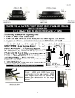
Front Burner
Adjust. Valve
Gas Inlets
WARNING: A SAFETY PILOT MUST BE INSTALLED ON ALL
UNITS DESIGNED
OR CONVERTED TO BURN PROPANE/LP GAS
Accessory Safety Pilot Lighting Kits:
• RPK1-F, RPK1-F10-F or EIS-N200
• RPK1-FA, RPK1-F10-FA or EIS-P200 (For use with Propane Gas Models
1. Assemble in accordance with specific instruction sheets provided with
SAFETY PILOT LIGHTING KIT
.
STEP TWO: Gas Connection.
ENSURE THAT GAS SUPPLY TO FIREPLACE IS TURNED OFF
1. Apply pipe compound to threaded end of
GAS SUPPLY PIPE (A)
. Thread
1/2"
MIP x 5/8" FLARE Fitting (B)
onto
GAS SUPPLY PIPE (A)
using a ½” 90-degree
Elbow fitting (not supplied) and wrench tighten.
2. Thread (without pipe compound) one end of the
FLEXIBLE CONNECTOR
TUBE (C)
to the
1/2" FIP x 5/8" FLARE ELBOW (B)
and wrench tighten.
3. Carefully bend
CONNECTOR TUBE (C)
and connect, without pipe compound,
to the
FLARED VALVE INPUT FITTING (D)
. Wrench tighten.
NOTE: CONNECTOR TUBE (C)
may kink or break, causing air flow noise and/or
leaks if bent into too small a radius.
4. Turn gas supply to fireplace on.
5. Test all connections for leaks with soapy water solution. If solution bubbles, turn
off gas supply, re-tighten fitting and recheck.
WARNING: DO NOT FLAME TEST FOR LEAKS.
.
A
B
Figure 4
Exterior
Gas Supply
Valve
TYPICAL
INSTALLATION
C
D
Note: LD30 and LD36 have one
connection to the gas supply. LD48
and larger have two to provide for
better gas distribution for the larger
sizes.
LD30 and LD36
Gas Inlet
LD30 and LD36
LD 48 and larger
Front Burner
Adjust. Valve
Front Burner
Adjust. Valve
Gas
Inlets (2)
f i r e - p a r t s . c o m


