Chapter 4: Connecting External Equipment (Optional)
47
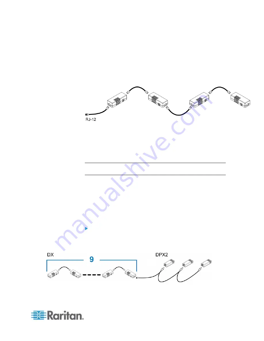
2. If you want to cascade DX packages, get an additional standard
network patch cable (CAT5e or higher) and then:
a. Plug one end of the cable into the remaining RJ-45 port on the
prior DX package.
b. Plug the other end into either RJ-45 port on an additional DX
package.
Repeat the same steps to cascade more DX packages.
3. Connect the first DX sensor package to the PX.
Plug the adapter cable's RJ-12 connector into the RJ-12
SENSOR port of the PX.
4. If needed, connect a DPX2 sensor package to the end of the DX
chain. See
Connecting a DPX2 Sensor Package to DX
(on page
Note: If your PX has "two" RJ-12 SENSOR ports, see
Guidelines for PX
with Two Sensor Ports
(on page 54) for sensor connection restrictions.
Connecting a DPX2 Sensor Package to DX
You can connect only one DPX2 sensor package to the "end" of a DX
sensor chain. It is strongly recommended to use an RJ-12 to RJ-45
adapter for connecting the DPX2 to the final DX in the chain.
The maximum number of DX sensor packages in the chain must be less
than 12 when a DPX2 sensor package is involved.
When connecting a DPX2 sensor package containing three
DPX2 sensors:
A maximum of nine DX sensor packages can be cascaded because
12-3=9.
Summary of Contents for PX2-1000 SERIES
Page 5: ......
Page 71: ...Chapter 4 Connecting External Equipment Optional 52...
Page 231: ...Chapter 6 Using the Web Interface 212 8 Click OK...
Page 589: ...Appendix I RADIUS Configuration Illustration 570 Note If your PX uses PAP then select PAP...
Page 594: ...Appendix I RADIUS Configuration Illustration 575 14 The new attribute is added Click OK...
Page 595: ...Appendix I RADIUS Configuration Illustration 576 15 Click Next to continue...
Page 627: ...Appendix K Integration 608 3 Click OK...
Page 647: ...Index 629 Z Zero U Connection Ports 74 Zero U Products 2...


