background image

C

HAPTER 

2:


O

PERATION


Chapter 2: Operation 

Customize the Paragon Manager Window 

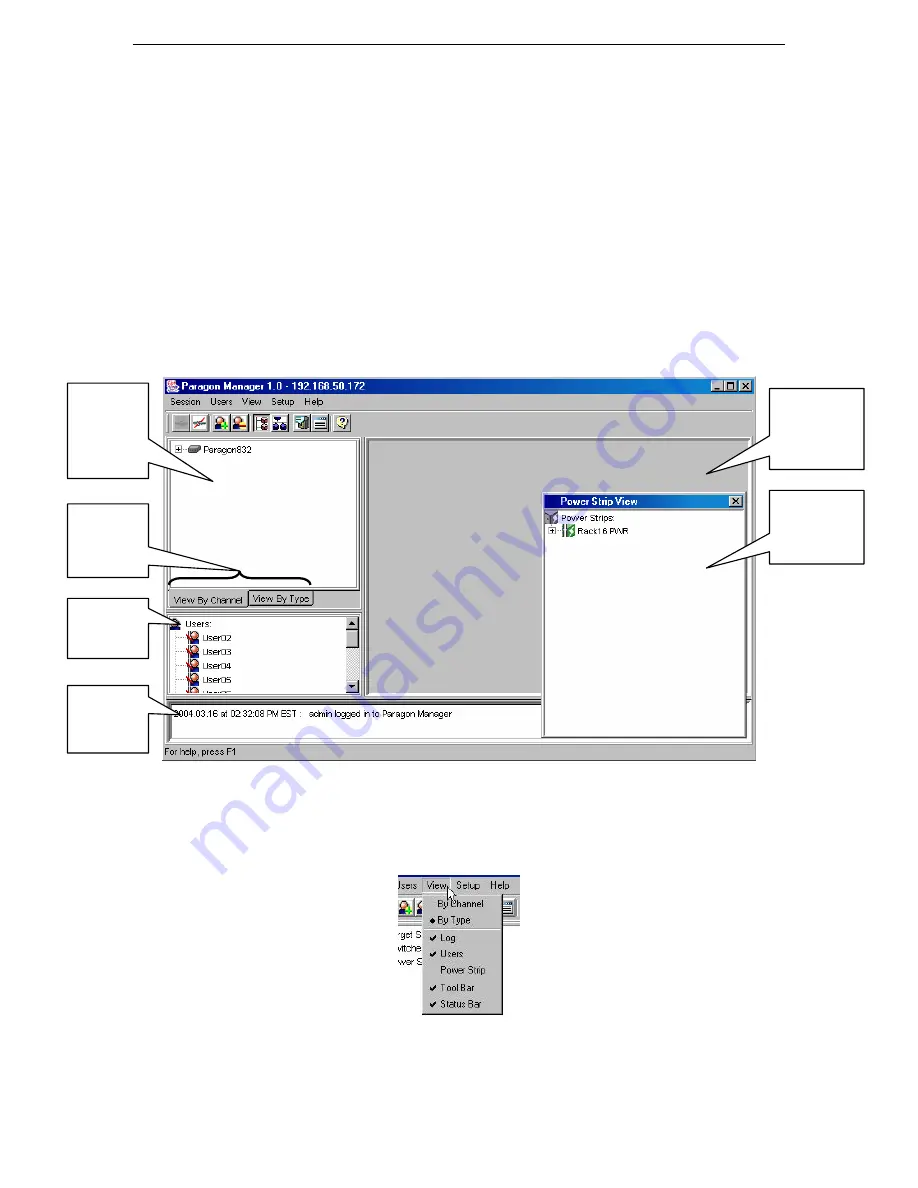
The Paragon Manager window contains the Paragon Manager menu bar and tool bar, the Device panel, 
User panel, Log panel, and Power Strip View window. You can customize your view by resizing panels or 
by viewing or hiding any of these components (except for the Device panel).  
The Device panel displays all connected devices in your Paragon system, and the User panel displays all 
users in your Paragon system. The Log panel displays the current activity of Paragon Manager. The Power 
Strip View panel displays any power strips connected in your Paragon configuration.  
When you connect to your Paragon unit via Paragon Manager, Paragon Manager downloads the Paragon 
unit’s database and populates the Device, User, and Power Strip panels. All data from the Paragon is visible 
in the Paragon Manager window. Once a session is initiated, updates to the database happen in real time 
and changes to the Paragon database from other users are immediately reflected in your Paragon Manager 
screen.  


Figure 4 Paragon Manager Window 

Display or hide any of these panels, except for the 

Device

 panel, by selecting options on the 

View 

menu; 

click on the desired panels in the menu to view or to hide them. A check mark before the menu item 
indicates that it is in view. By default, the 

Device

 panel cannot be hidden. 


Figure 5 View Menu (check marks indicates panels in view) 

Resize the window panels by resting your mouse cursor on the border of two panels until a double-headed 
arrow appears. Click and drag the arrow to size the panel up/down or left/right.  

Device Panel - 
displays all 
connected 
devices in the 
Paragon II 
system 

User Panel – 
displays users 
and groups in 
the system 

Log Panel – 
displays tracked 
events by date 
and time 

Power Strip View 
Window – 
displays power 
strips and 
connected ports


Device View 
Tabs – view all  
devices by 
Channel or by 
Type  

Multi-Function 
View (MFV) 
Panel – displays 
device and/or user 
information


Summary of Contents for Paragon Manager

Page 1: ...35 Pao Chiao Rd Hsin Tien Taipei Hsien Taiwan ROC Tel 886 2 8919 1333 Fax 886 2 8919 1338 E mail sales asia raritan com http www raritan com tw Raritan Computer France 120 Rue Jean Jaures 93200 Levall...

Page 2: ...This page intentionally left blank...

Page 3: ...ademark of Sun Microsystems All other marks are the property of their respective owners System Requirements Your system must meet these minimum requirements in order to run Paragon Manager Memory 256M...

Page 4: ...This page intentionally left blank...

Page 5: ...ofiles 8 Load Profiles 9 Device and User Panel Icons 9 Log Panel 10 Edit Event Log Settings 10 Power Strip Window 11 Edit a Power Strip 11 Power Strip Outlet Associations 12 Multi Function View MFV Pa...

Page 6: ...e 5 Figure 8 User Panel 6 Figure 9 Add User Window 6 Figure 10 Change Password Window 6 Figure 11 User Information Window 8 Figure 12 Select Destination Path Window 8 Figure 13 Confirm Load User Profi...

Page 7: ...tion is possible from a different room or from across the country using Paragon Manager Log On Please note that only Administrators have permissions to log on to Paragon Manager 1 On the Start menu cl...

Page 8: ...Select the Serial option button if you are using Paragon Manager with a UMT unit that has a serial admin DB9 port Click on the Port drop down arrow and select the port from the list f Click Save to s...

Page 9: ...on is initiated updates to the database happen in real time and changes to the Paragon database from other users are immediately reflected in your Paragon Manager screen Figure 4 Paragon Manager Windo...

Page 10: ...lete User Deletes the user selected in the User View window from Paragon Manager and the connected Paragon system View By Channel Displays the devices in the Device panel by Channel View By Type Displ...

Page 11: ...panded Target servers appear as computer icons Grey computer icons represent a target that is currently powered OFF and blue computer icons represent a target that is currently powered ON and therefor...

Page 12: ...ccount properties for users selected in this window Figure 8 User Panel Create a User 1 On the Users menu click Create The Add User window appears Figure 9 Add User Window 2 Type the new user s name i...

Page 13: ...ose None to override this capability Note that this option is set in Paragon Manager but is used anywhere in the Paragon system 9 Click on the Green Mode min drop down arrow and turn Green Mode Powers...

Page 14: ...inished click OK to change the user properties or click Cancel to close the window Save Profiles As an Administrator you can back up the User Database of the connected Paragon system to your local com...

Page 15: ...User Panel Icons ICON INDICATES Admin logged in and Connected Admin logged in and Disconnected Admin logged out and Disconnected User logged in and Connected User logged in and Disconnected User logg...

Page 16: ...before a device to select and specify events for recording in the log panel Select an event for the device 4 On the right side of the window click on the Set Severity Level drop down arrow and select...

Page 17: ...rganize the Power Strips in your Paragon configuration and to keep track of the machines to which they are connected you may want to name the Power Strips and outlets 1 Double click on any Power Strip...

Page 18: ...View MFV Panel The MFV panel of the screen displays detailed information of items you select in the Device panel User panel or Power Strip window and allows Administrators to edit item properties fro...

Page 19: ...you chose PC Share as your Operation Mode type a time period in seconds after which an inactive user is logged off a computer in the PCShareTimeout field 6 If you chose P View as your Operation Mode...

Page 20: ...ch displays the product name and version information you may need this information if you call Raritan Technical Support Disconnect and Exit Paragon Manager On the Session menu click Disconnect to dis...

Page 21: ...logged in and started a Paragon Manager session 1 On the Tools menu click Firmware Update 2 When notified that the Paragon unit session must be closed click Yes to proceed Figure 20Paragon Update Wind...

Page 22: ...e updated Make sure all the Paragon units in the system you wish to update are checked Please note that any connected Paragon II Stacking Switches will be automatically updated by the UMT to which the...

Page 23: ...n the Target Information window appears modify the information as needed Click OK to save changes How do I edit switch properties Switches are a little different since each switch will form an expanda...

Page 24: ...has been reached Paragon Manager will create a new log file to continue the logging process Click OK to save changes or click Restore to return Paragon Manager to its previous configuration How do I r...

Reviews: