background image

Raptor 3D Scanner Build Manual

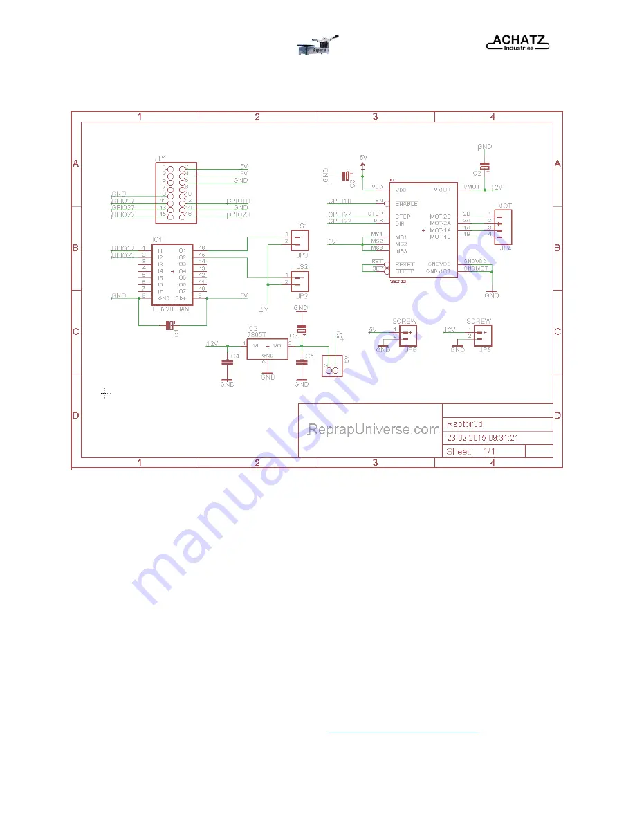
Appendix A (Schematics) 

Interface Board 

Keep strictly to the instructions as described on the images on page 22 of this Build Manual.

IT IS IMPORTANT THAT YOU CONNECT THE ELECTRONICS CORRECTLY. WRONG 
INSTALLATIONS CAN DESTROY YOUR ELECTRONICS! 

Stepper Motor Driver 

Pay careful attention to the direction of the A4988 stepper motor driver as wrong installation will 
destroy your electronics (see image on page 22 of this Build Manual).

Apply the heat sink to the stepper motor driver. 

Make sure you set the reference voltage of the stepper motor drivers to 0.5 - 0.6 V. You can find 
more information on the stepper motor drivers on: 

http://reprap.org/wiki/StepStick

Appendix A  -  (Wiring Diagram) 

29

Summary of Contents for 3D Scanner

Page 1: ...Raptor 3D Scanner BUILD MANUAL Raptor 3D scanner design documentation by Achatz Industries Haefland 8A 6441 PA Brunssum The Netherlands ...

Page 2: ...verse com Licensing Reprap GPL http reprap org wiki GPL This Document Copyright 2014 Achatz Industries All Rights Reserved Table of Contents Warnings Page 3 General Instructions Page 4 Step 1 Base Unit Page 5 Step 2 Raspberry Pi Camera Page 11 Step 3 Raspberry Pi B Page 13 Step 4 Power Supply Page 18 Step 5 Turn Table Page 20 Step 6 Interface Board Page 22 Software Instructions Page 24 Webinterfac...

Page 3: ...r in operation Liquid acetone and vapors are extremely flammable Pinch Hazard When the Raptor 3D scanner is in operation take care to never put body parts e g fingers into the moving parts turntable Make sure to tie back long hair or clothing that can get caught in the moving parts of the 3D scanner Static Charge Make sure to ground yourself before touching the electronics unit Electrostatic charg...

Page 4: ...nd take anti static precautions Level of Skill Building up the Raptor 3D scanner requires no advanced technical skills The Raptor 3D scanner is specifically designed to be a very easy to build 3D scanner There is no soldering required during the assembly of the 3D scanner as all connections are plug and play The electronic unit has already been prepared You will need to flash the software to the R...

Page 5: ...tor to the Raptor 3D scanner base plate using four M3x10 mm bolts and four M3L washers On the other side of the Raptor 3D scanner base plate mount four M3x20 mm spacers using four M3x10 mm bolts These M3 Spacers will be used for mounting the Raptor 3D scanner interface board Step 1 Base Unit 5 ...

Page 6: ...00 mm aluminium extrusions to the Raptor 3D scanner front plate using two M5x16 bolts and two M5S washer Slide eight t slot nuts through the aluminium extrusions Two on top and two t slut nuts on the outside of each extrusion Step 1 Base Unit 6 ...

Page 7: ...ing two M5x16 bolts and two M5S washers Please take note of the direction of the plate Now slide two t slut nuts on the top of the aluminium extrusions towards the side of the camera plate Take the base unit assembled in step 1 and position the t slot nuts to mount the plate Step 1 Base Unit 7 ...

Page 8: ...Manual Mount the base unit plate to the t slut nuts of the extrusions using four M5x12 bolts and four M5S washers Slide now the t slut nut from the side of the extrusions towards the end of the camera plate Step 1 Base Unit 8 ...

Page 9: ...tor 3D Scanner Build Manual Now mount the two side plates to the aluminium extrusions using two M5x12 bolts and two M5S washers for each side The direction of the plates does not matter Step 1 Base Unit 9 ...

Page 10: ... M3x12 spacers to the front of camera plate using four M3x10 bolts and four M3L washers Make sure you use the right holes Mount the laser plate to the camera plate using two M5x20 bolts and four M5S washers and two M5 nuts Step 1 Base Unit 10 ...

Page 11: ...m and remove the plastic protector from the lens Carefully insert the Raspberry Pi Cam into the opening of the camera plate Use the large plastic cover part to fix the camera Make sure you insert the plastic part the correct way and the holes are in line Step 2 Raspberry Pi Camera 11 ...

Page 12: ...Raptor 3D Scanner Build Manual Pull the cable of the Raspberry Cam over the larger printed part and secure it by using four M2x16 bolts eight M2 washers and four M2 nuts Step 2 Raspberry Pi Camera 12 ...

Page 13: ...tor 3D Scanner Build Manual Step 3 Raspberry Pi B Prepare the Raspberry Pi B unit Connect the cable to the Raspberry Pi B and make sure the red marked cable goes to the right side Step 3 Raspberry Pi B 13 ...

Page 14: ... Mount the Raspberry Pi B to the camera mount plate on the M3x12 spacers Secure the Raspberry Pi B with two M3x10 mm Display spacers on top marked in red and two M3x10 bolts on its bottom side marked in blue Step 3 Raspberry Pi B 14 ...

Page 15: ...canner Build Manual Connect the Raspberry Pi camera cable to the Raspberry Pi B Attach the Raspberry Pi casing printed part to the Raspberry Pi B using two M3x16 bolts and two M3S Washers Step 3 Raspberry Pi B 15 ...

Page 16: ...s two M3L washers and two M3 nuts for each side left right please note the M3S washer goes to the outside of the laser holder printed part Mount the line laser holder printed parts on each end of the laser plate by using two M3x25 bolts four M3L washers and two M3 nuts for each side Step 3 Raspberry Pi B 16 ...

Page 17: ...Raptor 3D Scanner Build Manual The correct angle of the line laser printed parts will be adjusted when the line lasers are installed Step 3 Raspberry Pi B 17 ...

Page 18: ...uild Manual Step 4 Power Supply Slide the cable of the Power Supply Unit through the hole of the camera plate Fix the Power Supply Unit to the camera plate using four M3x10 bolts and four M3S washer Step 4 Power Supply 18 ...

Page 19: ...Raptor 3D Scanner Build Manual Insert the two line lasers and fix the cabling with the two cable clips on each side Step 4 Power Supply 19 ...

Page 20: ... Scanner Build Manual Step 5 Turn table Attach the plastic part to the turn table plate using four M3x10 bolts and four M3 nuts Push the turntable onto the shaft of the NEMA 17 stepper motor Step 5 Turn Table 20 ...

Page 21: ...Raptor 3D Scanner Build Manual Attach the rubber cover over the turn table Step 5 Turn Table 21 ...

Page 22: ...e of the Raptor 3D scanner by using four M3x10 bolts Connect the electronics see image below IT IS IMPORTANT THAT YOU CONNECT THE ELECTRONICS CORRECTLY WRONG INSTALLATIONS CAN DESTROY YOUR ELECTRONICS Step 6 Interface Board 22 Left Laser Right Laser 12V 5V Raspberry Pi Caution Take care of the direction of the Raspberry Pi cable red marked cable directs to the right side Stepper Motor 12V 5V ...

Page 23: ...Raptor 3D Scanner Build Manual You have finished assembling your Raptor 3D scanner Step 6 Interface Board 23 ...

Page 24: ...i Insert the SD card into the Raspberry Pi SD card slot connect a Ethernet cable to the Raspberry Pi Power up the Raspberry Pi and wait a minute install Putty Check your router for Raspberry Pi s IP address run Putty setup a SSH connection entering the Raspberry Pi s IP x x x x Port 22 click Open login pi password raspberry enter from the Terminal sudo raspi config Select Enable camera and hit Ent...

Page 25: ...er Build Manual 3D Scanner Software For installing the scanner software open a browser window at your PC and goto https github com hairu freelss follow the instructions step by step at github Software Instructions 25 ...

Page 26: ...ur Browser and enter the Raptor 3D Scanner s IP address Go to the tab CAMERA and switch on the right and left laser Adjust the laser optic to the smallest possible line and align both laser units perfectly to the center of the turntable see image below Webinterface 26 ...

Page 27: ...Raptor 3D Scanner Build Manual Go to tabs SETTINGS and SETUP and enter the parameter settings as shown on the images below Webinterface 27 ...

Page 28: ...ptor 3D Scanner Build Manual You have successfully assembled and setup your Raptor 3D Scanner and are ready to go Please make sure to check the github directory frequently for new updates Webinterface 28 ...

Page 29: ...OUR ELECTRONICS Stepper Motor Driver Pay careful attention to the direction of the A4988 stepper motor driver as wrong installation will destroy your electronics see image on page 22 of this Build Manual Apply the heat sink to the stepper motor driver Make sure you set the reference voltage of the stepper motor drivers to 0 5 0 6 V You can find more information on the stepper motor drivers on http...

Page 30: ...D Scanner Front Plate Raptor 3D Scanner Camera Plate Raptor 3D Scanner Side Plate 1 Raptor 3D Scanner Side Plate 2 Raptor 3D Scanner Laser Plate 2x 1x 1x 1x 1x 1x 1x M2x16 Bolt M2 Washer M2 Nut Camera Cover Printed Part Large Camera Cover Printed Part Small Raspberry Pi Camera 4x 8x 4x 1x 1x 1x M3x10 Bolt M3x16 Bolt M3x25 Bolt M3S Washer M3L Washer M3L Washer M3 Nut 10 mm Display Spacer Laser Hold...

Page 31: ...rd Power Supply Unit ATX 400 W M3x10 Bolt M3S Washer Cable Clip Printed Part 1x 4x 4x 4x M3x10 Bolt M3 Nut Turn Table Mount Printed Part Turn Table Rubber Cover 4x 4x 1x 1x M3x10 Bolt Heat Sink Interface Board A4988 Stepper Driver Driver 4x 1x 1x Appendix B Illustrated Bill of Materials 31 ...

Reviews: