background image

10

Use Instructions

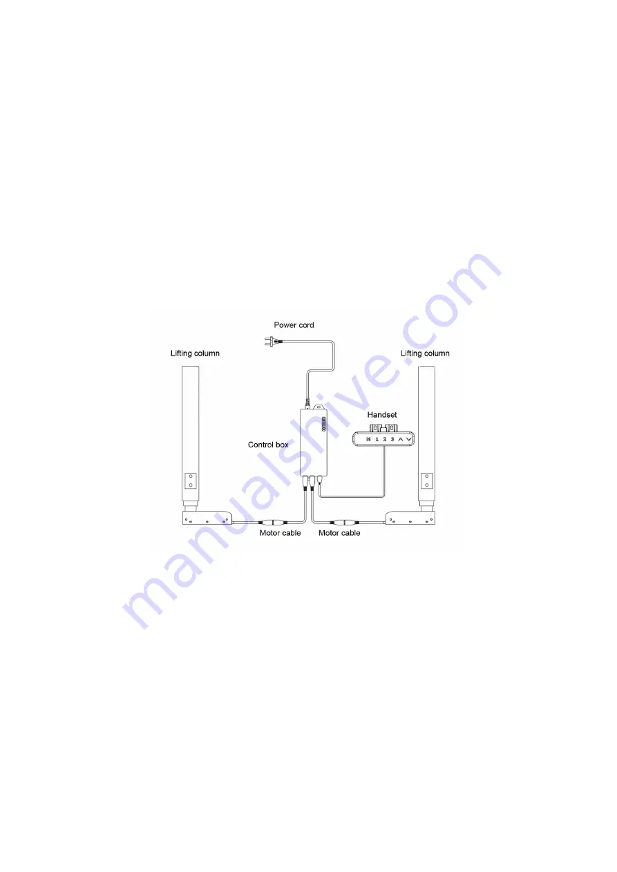
A. Parts list

1. Lifting Column ……................................................................................................................................. 2 pcs
2.Handset............................................................................................................................ 1 pcs
3. Control Box ……...................................................................................................................................... 1 pcs
4. Motor Cable …................................................................................................................................... 2 pcs
5. Power Cord …………............................................................................................................................... 1 pcs

Connect the cables as shown in the photo below:

B. Technical Specifications

Input: 100-240VAC
Output Power: 29VDC
Maximum accepted weight: 120 kg (including tabletop weight)
Maximum speed: 38 mm/s
Minimum height: 620mm
Travel distance: 650 mm
Operating temperature: 0-40°C
Duty Cycle: Max.10% or 2 min on and 18 min pause

Summary of Contents for Boost Plus FXBSTPBTB

Page 1: ...1 Back to back desk frame Instruction Manual Table of Contents Component parts 2 Assembly Instructions 3 Use Instructions 10 Troubleshooting 12 Important Safety Instructions 13 Advanced Programming 14 ...

Page 2: ...ts M8x10 9 3 Side Bracket 4 14 Connected beam 2 4 ST4x20 40 15 Centre bracket 2 5 Rubber pad 24 16 Allen Wrench 5mm 1 6 Bolts M6x12 10 17 Allen Wrench 4mm 1 7 Top frame 1 2 18 Cable Tie 10 8 Centre rails 4 19 Handset 2 9 Top frame 2 2 20 Control Box 2 10 Bolts M6x10 14 21 Motor cable 4 11 Screen brackets 4 22 Power cord 2 ...

Page 3: ...installed bolts and Adjust the length of the top frame to match the size of the table top Step 2 Inset the lifting column to the top frame First fix 2pcs screws M6x12 like B displayed And then tighten the pre installed bolts like C displayed A c B ...

Page 4: ...4 Step 3 Install the side brackets with Screws 8 pcs M6x16 Step 4 Install the leveling pads ...

Page 5: ... the connected pipe with 8 pcs screws M8x10 Step 6 Fix the screen brackets with 8 pcs screws M6x10 If you have a cable tray please refer to the page 7 for a cable tray installation before you do the following assembly ...

Page 6: ...op with 21 pcs screws ST4x20 Fix the handset with 2 pcs screws with ST4x20 Install the centre bracket with 2 pcs screws M6x10 Step 8 Mount the control box to the frame connected the cables well Zipped the cables with cable tie ...

Page 7: ...7 Cable tray installation Fix the cable tray with 8 pcs M6x10 screws to the desk frame ...

Page 8: ...8 Screen panel installation Step 1 Insert the tapped plates to the screen panel Step 2 Install the brackets to the panel with 8 pcs M5x6 screws ...

Page 9: ...9 Step 3 Fix the panel to the desk frame with 8 pcs M6x10 screws ...

Page 10: ... Cord 1 pcs Connect the cables as shown in the photo below B Technical Specifications Input 100 240VAC Output Power 29VDC Maximum accepted weight 120 kg including tabletop weight Maximum speed 38 mm s Minimum height 620mm Travel distance 650 mm Operating temperature 0 40 C Duty Cycle Max 10 or 2 min on and 18 min pause ...

Page 11: ... the current height to a number on the keypad Can be saved and memorized 3 different heights Moving the desk to a preset height can be done by pressing the corresponding button from 1 to 3 During operation you can stop the desk by pressing one of the UP DOWN buttons 5 Keypad Lock To lock Press and hold UP and DOWN buttons for 5 seconds until LOC sign appears on the display indicating that the syst...

Page 12: ...wo lifting columns is higher than 1 cm 0 4 inches Solution Start the Reset process 4 E07 Issue The load weight exceeds the limit of 120 kg Solution Remove some from the things on the desk to make sure the total weight does not exceed 120 kg 5 E08 Issue The input voltage is lower than the required value Solution The error code will automatically disappear when the voltage increases and reaches the ...

Page 13: ...onents away from liquids Never touch or handle the desk power supply the control box the panel control or any other cable with wet hands Clean the product only with a clean dry soft cloth or cloth Disconnect from the power supply before moving or cleaning electrical components Do not disassemble the columns control box and control panel These actions are considered damage caused by the user This p...

Page 14: ...ti collision sensitivity setting 16 5Fd Go down anti collision sensitivity setting 16 6FS Balance sensitivity 17 7SH Setting the new lowest display and height range 17 8Hc Setting Constant touch One touch 18 9St Time Reminder setting 18 10H Setting bounce height 18 11r Restore Factory Defaults 19 12d Fatigue test mode 19 ...

Page 15: ...d 3 seconds handset display S Release M button Press M button to enter Display 1Un 1 Press UP Down It will display 2br 2 Press M to enter It will display current brightness level Means normal brightness Means low brightness Means high brightness 3 Press UP or DOWN to select the desired brightness level press S button to confirm wait 2 seconds It will display current height 3bE Setting voice Press ...

Page 16: ...t the your favorite level Press M button to confirm wait 2 seconds It will display current height 5Fd Go down anti collision sensitivity The desk has an Anti Collision Sensitivity that will stop the desk s movement if it hits something on the way down You can change this Sensitivity level by doing the following Press M button and hold 3 seconds handset display S Release S button Press M button aga...

Page 17: ...and maximum height limits These steps allow the upper and lower limits to be adjusted to your preference Press M button and hold 3 seconds handset display S Release S button Press M button again to enter Display 1Un 1 Press UP or DOWN It will display 7FS 2 Press M button to enter It will display Press UP or DWON It will display and Set the lowest position height display Set a new minimum desk heig...

Page 18: ...nd up when you sit in a long time you can set it by doing the following Press M button and hold 3 seconds handset display S Release M button Press M button again to enter Display 1Un 1 Press UP or DOWN go get 9St 2 Press S to enter It will display 0 0H It no time reminder H means Hour 3 Press UP or DOWN to select the time reminder you need 1 5H means 1 5 hours Press S to confirm Note When handset ...

Page 19: ...lay S Release M button Press M button again to enter Display 1Un 1 Press UP or DOWN It will display 11r 2 Press M to enter It will display and flash 3 Press M to confirm wait 2 seconds It will display current height 12d Fatigue test mode Factory use please ignore this programming ...

Reviews: