background image

18

SECTION 11

OPERATING INSTRUCTIONS

BEAD LOOSENING AND DEMOUNTING

Remember to remove all weights from both sides of 

the wheel. Weights left on the back side of the wheel may 

cause the wheel to be clamped un-level. This may result in 

the combination mount/demount head contacting the rim

causing scratches. On alloy wheels, always rotate the 

wheel one turn after setting the head to insure proper wheel 

chucking.

u

 Always review nicks and scratches with owners of  

expensive wheel and tire combinations prior to servicing.

u

  Review the performance wheel section of this manual 

prior to servicing performance tire/wheel combinations.

1. Deflate tire completely by removing the valve core from 

the valve stem. (See Fig. 11.1).

2. The clamps on the table top may extend beyond the 

table top itself. To avoid damaging the clamps and/or 

wheel, move the clamps to their full inward position before         

positioning a tire for bead loosening.

3. Always loosen the bead on the narrow side of the wheels 

drop center first. (See Page 19 for better description of the 

drop center.)

4. Use extra care in positioning the bead breaker shoe on 

larger wheels/tires, and on alloy wheels. Make sure the 

shoe rests next to but not on the rim, and not on the tire 

sidewall.

5. Pull the bead breaker shoe away from the machine and 

roll the wheel into position. The valve stem should be in the 

2 o’clock position.

6. Position the bead breaker shoe against the tire next to, 

but not on, the rim. Press the breaker pedal to actuate the 

shoe and loosen the bead. It may be necessary to loosen 

the bead in multiple locations around the tire.

(See Fig. 11.2)

7. Turn wheel around and repeat procedure on the other 

side of the wheel. This should be the long side of the drop 

center. It will be easier to clamp the wheel to the table top if 

the lower bead is loosened last. (See Fig. 11.3)

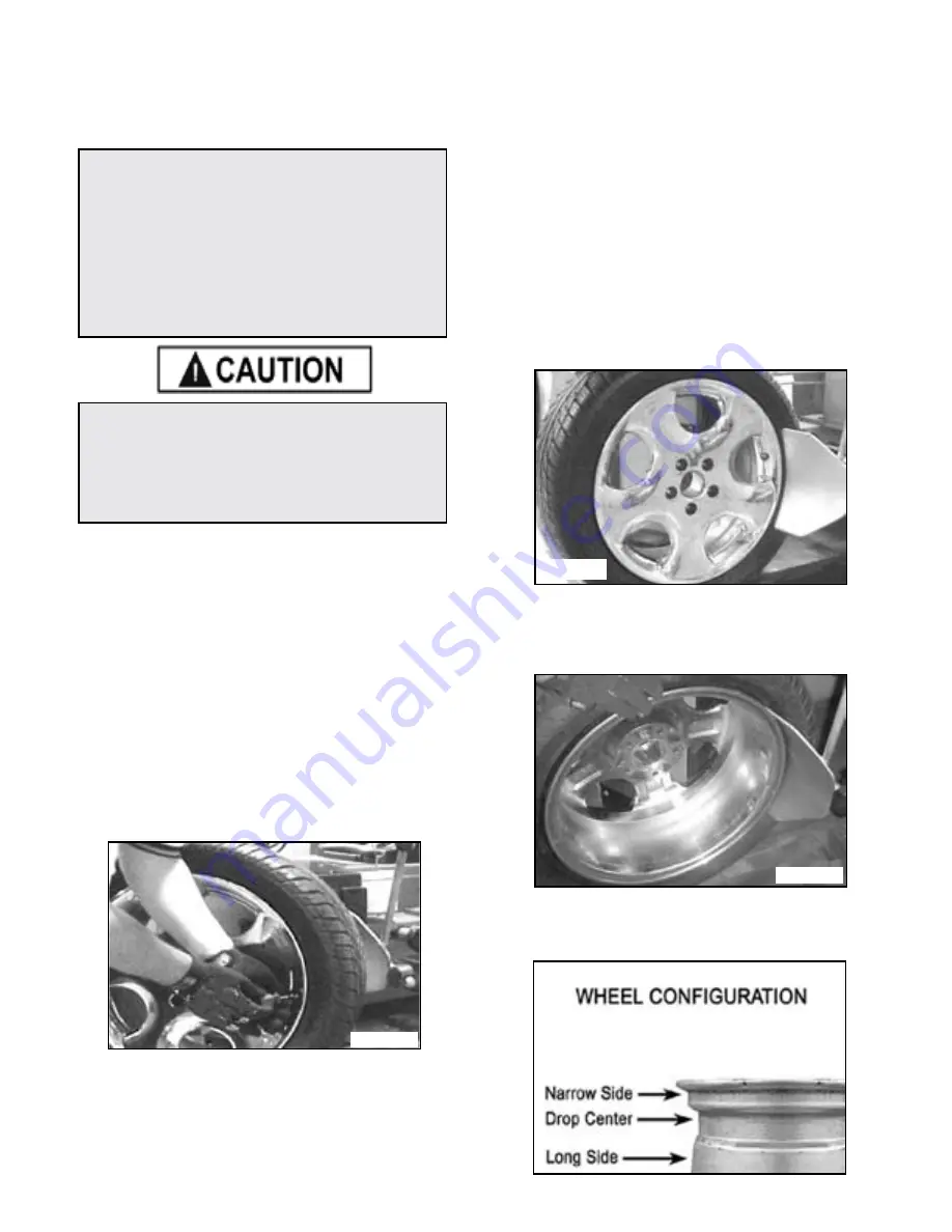
8. Determine the mounting side of the wheel. The 

mounting side is the narrow side of the drop center. The tire 

is removed for clarity. (See Fig. 11.4)

The unit must be properly operated and 

maintained to help avoid accidents that could 

damage the unit and injure the operator or 

bystanders. This section of the Operating 

Instructions manual review basic operations 

and use of controls. These instructions should 

be reviewed with all employees before they are 

allowed to work with the machine. 

Keep these instructions near the machine for 

easy reference.

CAUTION! 

This machine may operate differently from 

machines you have previously operated. 

Practice with a regular steel wheel and tire  

combination to familiarize yourself with the 

machine’s operation and function.

Fig. 11.1

Fig. 11.2

Fig. 11.3

Fig. 11.4

Summary of Contents for R23LT

Page 1: ...training and thoughtful operation on the part of the operator DO NOT operate or repair this equipment without reading this manual and the important safety instructions shown inside Keep this operatio...

Page 2: ...id which prove upon inspection to be defective The manufacturer will pay labor costs for the first 12 months only on parts returned as previously described The warranty does not extend to t defects ca...

Page 3: ...achine until you read and understand all the dangers warnings and cautions in this manual For additional copies or further information contact BendPak Inc Ranger Products 1645 Lemonwood Dr Santa Paula...

Page 4: ...nstallation instructions t Make sure installation conforms to all applicable Local State and Federal Codes Rules and Regulations such as State and Federal OSHA Regulations and Electrical Codes t Caref...

Page 5: ...ive terminal This is for ground only 11 DANGER The motor on this machine contains high voltage Disconnect power at the receptacle before performing any electrical repairs Secure plug so that it cannot...

Page 6: ...ds before demounting or mounting and seating the beads NEVER mount a tire on a damaged or rusty wheel as tire or wheel failure may result during inflation Explosion from failure may result in severe i...

Page 7: ...3 Assist Arm Control Pod 14 Horizontal Vertical Slides 15 Slide Adjustment Handle 16 Left Helper Restraint Head 17 Combination Mount Demount Head 18 Table Top Clamps 19 Turntable 20 Tilt Back Tower Pe...

Page 8: ...rd Internal Wheel clamping Capacity 11 24 279 mm 610 mm External Wheel clamping Capacity 10 23 254 mm 584 mm Turntable Tire Width Capacity Mounting 4 5 17 5 114 mm 444 mm Bead Breaker Tire Width Capac...

Page 9: ...ontact with packing materials Eye protection is essential during uncrating service activity Safety glasses with side shields goggles or face shields are acceptable Remember to report any shipping dama...

Page 10: ...ing of the machine must be performed only with an appropriate lifting device such as a forklift or shop crane Only personnel who are experienced and qualified on material handling procedures should ha...

Page 11: ...and should be away from oil grease brake lathe chips etc Avoid areas where bystanders and customers may be present Machine size is approximately 48 W x 50 D X 80 H R23 AT DANGER These measurements ar...

Page 12: ...d set the Air Oil Regulator Assembly aside See Fig 8 5 CAUTION Handling of the machine must be performed only with an appropriate lifting device such as a forklift or shop crane Only personnel who are...

Page 13: ...Hook Secure with the Snap Rings See Fig 8 10 11 Feed The Tilt Tower Air Line through the hole in the Top of the base Cabinet as shown See Fig 8 11 12 Align the Cylinder Shaft and cylinder pin and hol...

Page 14: ...net See Fig 8 15 18 Reinstall the Side Cover Bead Breaker Blade 1 Attach the Bead Breaker Blade to the Bead Breaker Arm Assembly Secure the Nyloc nut See Fig 8 16 Demount Head Assembly 1 Check that th...

Page 15: ...ne A 1 4 ID hose or pipe for connection to the machine is satisfactory Sufficient air pressure assures good performance 1 Connect the Air Supply to the Air Drier Oiler A proper fitting not supplied to...

Page 16: ...cal requirements Have a licensed electrical technician perform any necessary changes to the power source and power cord before plugging in the unit The electrical source must have a solid connection b...

Page 17: ...protect the operator from electric shock Never connect the green power cord wire to a live terminal This is for ground only DANGER The motor on this machine contains high voltage Disconnect power at...

Page 18: ...t on the tire sidewall 5 Pull the bead breaker shoe away from the machine and roll the wheel into position The valve stem should be in the 2 o clock position 6 Position the bead breaker shoe against t...

Page 19: ...arrow Side and Wide Side flanges 3 The tire must ALWAYS be demounted or mounted with the wheel positioned on the turntable with the Narrow Side facing upward and the deepest part of the Drop Center fa...

Page 20: ...er bead helpers to assist in the bottom bead lubrication See Fig 11 8 13 Move the tower forward by depressing the Tower Tilt Pedal then press the control button to unlock the horizontal slide Pull the...

Page 21: ...Insert the smooth curved end of tool bar over the right end knob of the mount demount head and below the top bead of the tire See Fig 11 19 11 20 20 Push the tool bar down toward the wheel to lift th...

Page 22: ...wheel to lift the tire bead up and over the right side knob portion of the demount head Hold the tool bar in this position See Fig 11 27 11 28 24 Depress the table top pedal to rotate the wheel The de...

Page 23: ...ifting tool as described earlier paying careful attention not to pinch the tube Depress the table top pedal and rotate only a short distance at a time This allows you to stop the process should you su...

Page 24: ...emount head and below the right front knob See Fig 13 4 5 Manually force the tire down into the drop center of the wheel directly across from the mount head to reduce the tensional force on the bead D...

Page 25: ...ifting tool as described earlier Mount the bottom bead first 3 Round out the tube with a small amount of air Avoid pinching or forcing the tube Apply rubber lubricant to the tube 4 Insert the tube int...

Page 26: ...ION GAUGE FOR PROPER OPERATION ACCURATE PRESSURE READINGS ARE IMPORTANT TO SAFE TIRE INFLATION REFER TO THE OPERATING MAINTENANCE SECTION OF THIS MANUAL FOR INSTRUCTIONS DANGER THE CLIP ON AIR CHUCK O...

Page 27: ...See Fig 16 5 16 6 STAGE TWO BEAD SEALING 1 Remove the Valve Stem Core and position Valve Stem and connect the Inflation Hose See Fig 16 7 2 Hold tire up against upper edge of the wheel Be sure tires...

Page 28: ...e air flow into the tire to assist with bead seal After bead seal is achieved remove the chuck and reinstall the valve core TIRE INFLATION The unit is equipped with a pressure limiter regulator to ass...

Page 29: ...seat Keep hands arms and entire body away from tire during this procedure Tire beads should move outward and pop into their bead seat position as pressure inside the tire increases If this does not ha...

Page 30: ...ND WHEEL COMBINATIONS CAN EXPLODE CAUSING PERSONAL INJURY OR DEATH TO OPERATOR AND BYSTANDERS FOR SAFETY DO NOT ATTEMPT TO MOUNT AND INFLATE MIS MATCHED TIRES AND WHEELS DANGER NEVER INCREASE AIR PRES...

Page 31: ...ers are in place t Check for worn damaged or missing parts including grips and protective covers Replace them before allowing the unit to be used MONTHLY t The vertical and horizontal slides and the h...

Page 32: ...lass Remove the reservoir by turning counter clockwise and pulling down Add SAE 10W non detergent oil or an air tool oil if necessary 4 Reconnect the air when service adjustments are complete Oiler Ad...

Page 33: ...so that it cannot be accidentally plugged in during service 1 Remove the Side Panel See Fig 17 8 2 Loosen the four Motor mounting adjusting bolts and nuts See Fig 17 9 3 Inspect the Drive Belt for cra...

Page 34: ...ceeds 60 PSI adjust the knob on the regulator by lifting the locking cover and turning COUNTERCLOCKWISE After adjustment is made secure cover in the locked position 6 Repeat steps 1 6 Re adjust if nec...

Page 35: ...35...

Page 36: ...36...

Page 37: ...ion 129 T Union 130 Cable holder 12 131 Screw M10 40 132 Pin 6X40 133 Tire changer body plug 134 Screw M10 135 Bolt M12 70 136 Washer 12 137 Voltage selector switch wires 138 Sope brush 139 Plastic st...

Page 38: ...38...

Page 39: ...ead insert 224 M10 X 20 Duckhead set screw 225 Duckhead retaining washer 226 Washer 10 227 Bolt M10 20 228 Roller insert 229 Duckhead roller 230 Pin 5X22 231 Roller pin M6 6 232 Tower assy unit 233 He...

Page 40: ...40...

Page 41: ...d 302 17 Jaw clamp cylinder body 302 18 Jaw clamp cylinder wear strip 302 19 O ring 25X3 1 303 Small cylinder cover 304 Seeger ring 12 305 Square turntable press pin 306 Metal Bushing 18X12X11 307 Was...

Page 42: ...42...

Page 43: ...rol valve straight 423 Quick relief valve 424 Quick relief valve spacer 425 Union G1 8 10 426 Quick relief valve 427 Relief valve seal cup 427 1 Relief valve assembly 428 Bead breaker blade knob 429 B...

Page 44: ...44...

Page 45: ...519 Gearbox back flange 520 Bearing 80208 521 Helical gear 522 Turntable key 12X8X35 523 bearing 80110 524 Gearbox front flange 525 Screw M8 30 526 BoltM10X180 527 Oil fill tube 528 Oil fill tube plug...

Page 46: ...46...

Page 47: ...Spacer 6 629 Pin 3X25 630 Directional switch cam linkage 631 Turntable directional switch cam 632 Screw M6 12 633 Washer M6 X 12mm flat 634 Washer M6 flat 635 Directional switch bracket 636 Direction...

Page 48: ...48...

Page 49: ...iled hose 8mm air 721 1 Inflation hose assy 722 Air chuck 723 Union 724 Union G1 8 8 725 Block 726 Screw M6 20 727 Washer M6 X 12mm flat 728 Washer 6 729 Self tapping screw M4X16 730 Turbo blast nozzl...

Page 50: ...50...

Page 51: ...829 Y ring94X84X6 830 O ring 14X2 5 831 Assist tower cyl piston 832 Left assist tower cyl rod 833 Washer 8 834 Screw M6 10 835 Left assist tower cyl cover 836 Quick union G1 4 6 837 Turbo blast hook...

Page 52: ...Parts Or Service Contact BendPak Inc Ranger Products 1645 Lemonwood Dr Santa Paula CA 93060 Tel 1 805 933 9970 Toll Free 1 800 253 2363 Fax 1 805 933 9160 www bendpak com www rangerproducts com pn 59...

Reviews: