background image

INSTALLATION

Check the appliance is electrically safe and gas sound when you have finished.

25

25

Conversion to Another Gas

If the appliance is to be converted to another gas do the 

conversion at this point. See the conversion section of these 

instructions.

Levelling

You are recommended to use a spirit level on a shelf in one of 

the ovens to check for level.
Place the cooker in its intended position taking care not to 

twist it within the gap between the kitchen units as damage 

may occur to the cooker or the units.
The front feet and rear rollers can be adjusted to level the 

cooker. 
To adjust the height of the rear of the cooker use a 13 mm 

spanner or socket wrench to turn the adjusting nuts at the 

front bottom corners of the cooker.
To set the front, turn the feet bases to raise or lower.

Gas Connection

This must be in accordance with the relevant standards.
The flexible hose (not supplied with the cooker) must be 

in accordance with the relevant standards. Hoses may be 

purchased at most builders’ merchants.
The gas supply needs to terminate with a down-facing 

bayonet.
The connector is located just below the hotplate level at the 

rear of the cooker. If in doubt contact your supplier.
The rear cover boxes limit the position of the supply point.
Because the height of the cooker can be adjusted and 

each connection is different, it is difficult to give precise 

dimensions.
Although a 900 mm hose can be used, a 1250 mm hose 

will allow slightly more flexibility in the positioning of the 

bayonet and make moving the cooker easier.
The hose should be fitted so that both inlet and outlet 

connections are vertical so that the hose hangs downwards in 

a ‘U’ shape.
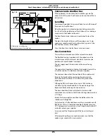
Ideally the hose supply connection should be within the 

shaded area ‘A’ 

(

Fig.7.10

)

.

For Natural Gas, the flexible hose must be in accordance with 

BS 669. For LP Gas, it should be capable of 50 mbar pressure, 

70 °C temperature rise, and carry a red stripe, band or label. If 

in doubt contact, your supplier.
Screw connect the threaded end of the hose into the gas 

inlet.
After completing the gas connection, make sure that the 

cooker is gas sound with a pressure test.

All dimensions in millimetres

Alternatively connect from the side.

100

200

Gas inlet block

A

350

550

Fig.7.10


Summary of Contents for Toledo XT 110 Dual Fuel

Page 1: ...Britain s No 1 Range Cooker USER GUIDE INSTALLATION INSTRUCTIONS Toledo XT 110 Dual Fuel...

Page 2: ...ar and serve immediately with cream or cr me fraiche FRUITY BAKED PUDDING Serves 4 6 Ingredients 3kg 6 lb skinned and boned loin of pork 2 x 70g packs prosciutto Grated zest of 2 lemons Bay leaves Sal...

Page 3: ...ate Burners 16 Control Panel and Doors 17 Ovens 17 Cleaning Table 18 6 Troubleshooting 19 7 Installation 21 Dear Installer 21 Safety Requirements and Regulations 21 Provision of Ventilation 21 Locatio...

Page 4: ...iv...

Page 5: ...respiratory or allergy problems should vacate the area for this brief period If you smell gas DO NOT turn electric switches on or off DO NOT smoke DO NOT use naked flames DO turn off the gas at the me...

Page 6: ...fat overheating beyond the smoking point n n WARNING n n Unattended cooking on a hob with fat or oil can be dangerous and may result in fire n n NEVER leave a chip pan unattended Always heat fat slow...

Page 7: ...flame goes out When the ignitor button is pressed in sparks will be made at every burner this is normal Do not attempt to disassemble or clean around any burner while another burner is on otherwise a...

Page 8: ...unstable and misshapen pans that may tilt easily and pans with a very small base diameter e g milk pans single egg poachers Fig 2 7 The minimum recommended pan diameter is 120 mm The maximum allowabl...

Page 9: ...o not put it crossways it will not fit properly and will be unstable Fig 2 12 n n Do not put it on any other burner it is not designed to fit in any of the other pan supports Position the griddle over...

Page 10: ...most of your cooking The browning element and base heat can be used in the latter part of the cooking process to fine tune the results to your particular requirements Use fanned grilling for all your...

Page 11: ...ur previous cooker Multi function Oven Functions Defrost This function operates the fan to circulate cold air only Make sure the temperature control is at 0 C and that no heat is applied This enables...

Page 12: ...knob to the temperature required Fig 2 17 The oven heating light will glow until the oven has reached the temperature you selected It will then cycle on and off during cooking as the oven maintains t...

Page 13: ...n the display 2 Once the stop time is reached the beeper sounds 3 To stop the beep turn the oven control knob to 0 first and then press B once press B again to return to manual cooking To Start and St...

Page 14: ...en On appears on the display Fig 2 30 press the button once The key symbol F and OF will now show on the display Fig 2 31 Release the buttons 3 The left hand oven is now locked as confirmed by the dis...

Page 15: ...or closed The racking on the inside of the multi function oven door left hand oven allows you to position the Handygrill at any of four different levels Using the Handygrill for fan grilling gives you...

Page 16: ...e unstable Fitting the Handygrill 1 Line up the ends of the Handygrill rack with a pair of holes in the mounting brackets on the oven door Fig 2 40 2 Slide the ends into both uprights at the same time...

Page 17: ...Ensure a soft cushioned mat is placed on the floor and covers the width and depth of the Storage Drawer 2 Slide the Storage Drawer out until it stops 3 Unscrew the two fasteners and remove the screw w...

Page 18: ...g on them should be placed level with the front edge of the oven s wire shelves Other containers should be placed centrally Keep all trays and containers away from the back of the oven as overbrowning...

Page 19: ...0 minutes according to size 2 3 hours 45 60 minutes 40 45 minutes 2 to 3 hours 20 30 minutes 15 20 minutes 15 20 minutes per 500g Steaks according to thickness Conventional Oven Temperature C Shelf Po...

Page 20: ...put the burner heads in a dishwasher Make sure they are absolutely dry before replacing them The Single Ring Burners When refitting the burner head make sure that the notch lines up with the electrod...

Page 21: ...rs to clean the oven door glass since they can scratch the surface which may result in shattering of the glass Cook Clean Panels The ovens have side Cook Clean panels which have been coated with a spe...

Page 22: ...cloth supermarket Sides and plinth Painted surface Hot soapy water soft cloth Splashback rear grille Enamel or stainless steel Hot soapy water soft cloth Cream cleaner with care if necessary Control p...

Page 23: ...mber to reset the clock to make sure that the timed oven continues to operate Food is cooking too slowly too quickly or burning Cooking times may differ from your previous oven Check that you are usin...

Page 24: ...ing care to protect your fingers with a glove in case the bulb should shatter unscrew the old bulb Screw in the new bulb screw back the bulb cover Turn on the circuit breaker and check that the bulb n...

Page 25: ...ion and Use regulations The relevant Building IEE regulations In the Republic of Ireland the cooker must be installed in accordance with The installation must be carried out by a competent person and...

Page 26: ...badge this will identify the gas type for which the appliance is now set You will need the following equipment to complete the cooker installation satisfactorily Stability bracket If the cooker is to...

Page 27: ...stant Certain types of vinyl or laminate kitchen furniture are particularly prone to heat damage and discolouration We cannot accept responsibility for damage caused by normal use of the cooker to any...

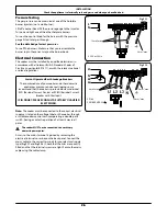
Page 28: ...hould be kept as short as is practicable and fixed firmly to the rear of the cooker If you are using a stability bracket Fig 7 8 and Fig 7 9 then adjust the bracket to give the smallest practicable cl...

Page 29: ...ants The gas supply needs to terminate with a down facing bayonet The connector is located just below the hotplate level at the rear of the cooker If in doubt contact your supplier The rear cover boxe...

Page 30: ...tic appliances may cause nuisance tripping so we recommend that the cooker is protected on an individual RCD Residual Current Device or RCBO Residual Current Breaker with Overload IF IN DOUBT PLEASE C...

Page 31: ...eck that the oven fans start to turn and that the ovens start to heat up Note The oven light bulb is not included in the guarantee Turn off the oven Final Fitting Fitting the Plinth Loosen the 3 screw...

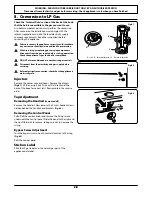
Page 32: ...icity and gas supply before servicing n n Before electrical reconnection check that the appliance is electrically safe Injectors Remove the burner caps and heads Remove the old jets Fig 8 1 Fit the ne...

Page 33: ...e of the left hand hotplate burner jets Lift off a burner head Fit the pressure gauge to the jet Turn on and light one of the other burners with a match Turn on and press in the control knob for the b...

Page 34: ...n yellow gr Grey 9 Circuit Diagram Code Description A1 Left hand Multi function oven thermostat A2 Left hand multi function oven function control A3 Left hand Multi function oven base element A4 Left...

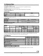
Page 35: ...urner 57 3 5kW internal 78 3 5kW 246g h internal 53 external 126 external 82 Large burner 40 3 0kW 134 3 0kW 210g h 87 Medium burner 32 1 7kW 109 1 7kW 119g h 68 Small burner 28 1 0kW 75 1 0kW 70g h 5...

Page 36: ...32 Notes...

Page 37: ...33 Notes...

Page 38: ...34 Notes...

Page 39: ...those authorised to act on behalf of AGA Rangemaster Exceptions Items not included under the free 1 year warranty include pan supports griddles wok rings baking trays grill pans trivets filters light...

Page 40: ...ed Office Juno Drive Leamington Spa Warwickshire CV31 3RG Search Rangemaster UK Rangemaster continuously seeks improvements in specification design and production of products and thus alterations take...

Reviews: