


29
8. Circuit Diagrams
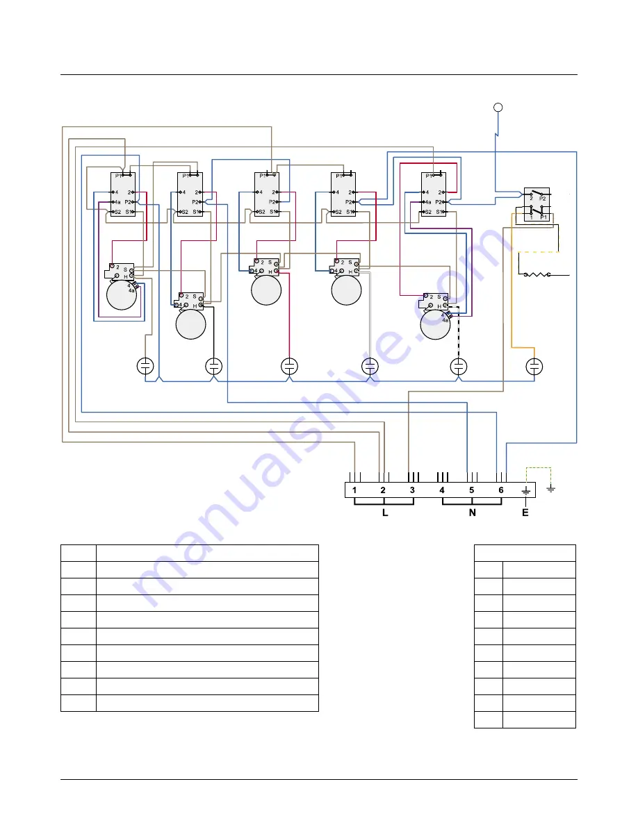
Circuit Diagram: Hob
(with warmer plate)
ArtNo.095-0003 - Circuit diagram - 90 induction
ArtNo.082-0023 - 110 Ceramic (hob warmer only) - circuit diagram
������
�����
������
�����
������
��
��
���
��
��
�
� �
��
��
�
��
�
�
�
�
�
�
�
�
��
�
�
�
�
�
�
�
��
��
��
��
�
�
�
�
��
��
��
��
�
�
��
�
��
�
�
�
�
��
��
�
��
��
�
�
��
�
��
��
�
�
��
��
��
�
�
����
�
�
�
�
��
��
���
��
��
��
���
�
�
�
�
�
��������������
�
�
�
�
�
�
�
�
Code Description
A
Left-hand end dual circuit hob energy regulator
B
Left-hand front hob energy regulator
C
Left-hand rear hob energy regulator
D
Right-hand rear hob energy regulator
E
Earth terminal
F
Right-hand front hob dual energy regulator
G
Right-hand warmer hob controller
H
Hob neons
J
Warmer
Colour Code
b
Blue
br
Brown
bk
Black
or
Orange
r
Red
v
Violet
w
White
y
Yellow
g/y
Green/yellow
bk/w
Black/white
Connections shown in the circuit diagram are for single-phase. Ratings are for 230V 50Hz


