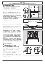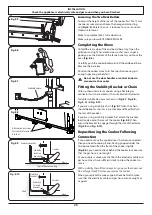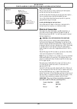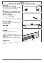
WARNING – SERVICING TO BE CARRIED OUT ONLY BY AN AUTHORISED PERSON
Disconnect from electricity and gas before servicing. Check appliance is safe when you have finished.
31
Turn the bypass screw on each control clockwise to the stop
Oven Thermostat Bypass
Remove the thermostat bypass screw and fit the new one for
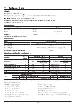
each oven (see the ‘Technical Data’ section of this book for the
correct bypass screws).
Refit the control panel.
Grill
Injector
Lift up the spring retaining the grill holder and slide the jet
holder out of the burner venturi (Fig. 9.7). Remove the grill
jet from the adaptor and fit a new jet (see the ‘Technical Data’
section of this book for the correct jets). Refit the jet holder
back into the burner venturi.
Ovens
Oven Burner Injector
Remove the oven furniture. Remove the securing screw at the
right-hand end of the burner assembly (Fig. 9.8). The burner
is held in place by dimples in the mounting bracket. Slide the
burner to the left and lift up, taking care not to disturb the
ignition electrode or the flame supervision device electrode
positions.
Remove the oven jet from the adaptor and fit the new jet
(Fig. 9.9) (see the ‘Technical Data’ section of this book for the
correct jets).
Reassemble in the reverse order.
Stick on Label
Stick the conversion gas label over the natural gas part of the
appliance data label.
Pressure Testing
Connect the appliance to the gas supply.
The gas pressure can be measured at one of the hotplate
injectors (not a wok burner).
Lift off a burner head. Fit the pressure gauge to the jet. Turn
on and light one of the other burners. Turn on and press in
the control knob for the burner with the pressure gauge
fitted.
The pressure should be 29 mbar for Butane and 37 mbar for
Propane. After checking the pressure, turn off the taps and
replace the burner head.
Reassemble burner top, making sure it is reassembled in the
correct way on the burner body.
Check operation of all the burners.
Check the appliance is gas sound.
ArtNo.333-0005 - 90 Bray gas
grill injector - change jet
Fig. 9.7
Fig. 9.8
Fig. 9.9
ArtNo.0102-0011 - Screwing
the control valve bypass screw
Fig. 9.6


