background image

  15

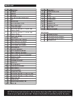
PARTS LIST

NOTE: Some grill parts shown in the assembly steps may differ slightly in appearance from
those on your particular grill model. However, the method of assembly remains the same.

Key Qty Description

A

1

FIREBOX

B

1

IGNITOR

C

1

BURNER

D

1

COLLECTOR/ ELECTRODE ASSY

E

1

LID

F

1

LOGO PLATE

G

1

LEFT SIDE SHELF F/ SB

H

1

RIGHT SIDE SHELF

I

1

TANK

 RETAINER

J

1

MOUNTING BRACKET, F/ PLASTIC SIDE 
SHELF, (LF/RB)

K

1

MOUNTING BRACKET, F/ PLASTIC SIDE 
SHELF, (RF/LB)

L

2

C

ART LEG,UPPER 

M

1

SIDE BRACE 

N

1

RIGHT FRONT LEG, CURVED

O

1

RIGHT BACK LEG, STRAIGHT

P

1

LEFT BACK LEG, STRAIGHT

Q

1

LEFT FRONT LEG, CURVED

R

2

BACK

 BRACE

S

2

SUPPORT BRACKET

T

1

LEFT 

FIREBOX SUPPORT

U

1

RIGHT 

FIREBOX SUPPORT

V

1

VALVE HOSE REGULATOR ASSEMBLY

W

1

CONTROL PANEL

X

1

FRONT PANEL

Y

1

CONDIMENT BASKET

Z

1

AXLE ROD

AA

2

LEG EXTENDER

BB

3

TANK EXCLUSION WIRE

CC

1

HEAT SHIELD

DD

2

COOKING GRATE

EE

1

SWINGAWAY GRID

FF

1

MOUNTING BRACKET, F/ SHELF, (LF/ RB)

GG

1

MOUNTING BRACKET, F/ SHELF, (RF/ LB)

HH

1

DRIP PAN F/ SB

II

1

SIDEBURNER

JJ

1

ELECTRODE W/ WIRE, F/ SB

KK

1

LID F/ SB

Key Qty Description

LL

1

SIDEBURNER GRATE

MM

2

WHEEL

NN

3

KNOB

OO

2

LOWER HINGE

PP

2

UPPER HINGE

QQ

1

HANDLE

RR

1

GREASE CUP

SS

1

GREASE CUP CLIP

TT

1

HEAT TENT

UU

1

M

ATCH HOLDER

1

HARDWARE PACK

1

ASSY INSTRUCTION, ENGLISH

1

ASSY INSTRUCTION, SPANISH

1

RETAINER CLIP

NOT Pictured

Summary of Contents for 463722512

Page 1: ... below See rating label on grill for serial number 02 07 12 G305 001 350801 Printed in China Estimated assembly time 35 40 minutes If you have questions or need assistance during assembly please call 1 800 241 7548 PRODUCT GUIDE MODEL 463722512 Assembly instructions 2012 C 23G3CB ...

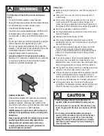
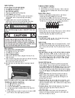
Page 2: ...ly hazardous situation or unsafe practice which if not avoided may result in minor or moderate injury Safety Symbols The symbols and boxes shown below explain what each heading means Read and follow all of the messages found throughout the manual DANGER If you smell gas 1 Shut off gas to the appliance 2 Extinguish any open flame 3 Open lid 4 If odor continues keep away from the appliance and immed...

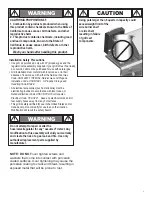
Page 3: ...l electrical accessories such as rotisserie must be electrically grounded in accordance with local codes or National Electrical Code ANSI NFPA 70 or Canadian Electrical Code CSA C22 1 Keep any electrical cords and or fuel supply hoses away from any hot surfaces This grill is safety certified for use in the United States and or Canada only Do not modify for use in any other location Modification wi...

Page 4: ... You can inadvertently activate this safety feature without having a gas leak This typically occurs when you turn on the gas using the grill control knob before you turn on the LP tank valve If the gas regulator safety feature activates the grill will only reach temperatures between 250 F and 300 F even with all burners on the high setting If your grill is not getting hotter than 250 F to 300 F th...

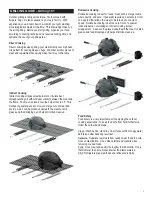
Page 5: ...rneath the meat to catch grease and food drippings and helps minimize clean up Rotisserie Cooking Rotisserie cooking is best for round meat such as large roasts whole poultry and pork It generally requires an accessory motor and spit rod that allows the meat to be turned at a constant speed Rotisserie cooking is best done in front of a special rotisserie burner or utilizing an indirect cooking bur...

Page 6: ...n be applied directly to the meat immediately before grilling www isitdoneyet gov GRILLING GUIDE Tips Tricks Wood Chips For extra smoke flavor when grilling try adding wood chips Soak the chips in water for approximately 30 minutes before adding to a smoke box or pan Place smoke box or pan on top of the cooking grate above the flame Turn grill on high until the wood starts to smoke Reduce heat to ...

Page 7: ...Stainless steel can rust under certain conditions This can be caused by environmental conditions such as chlorine or salt water or improper cleaning tools such as wire or steel wool It can also discolor due to heat chemicals or grease build up To maintain your grill s high quality appearance wash with mild detergent and warm water or use a stainless steel grill cleaner Baked on grease deposits may...

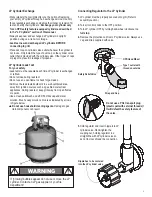
Page 8: ...der Filling Use only licensed and experienced dealers LP dealer must purge new cylinder before filling Dealer should NEVER fill LP cylinder more than 80 of LP cylinder volume Volume of propane in cylinder will vary by temperature A frosty regulator indicates gas overfill Immediately close LP cylinder valve and call local LP gas dealer for assistance Do not release liquid propane LP gas into the at...

Page 9: ...as described in the LP Cylinder section of this manual Always keep new and exchanged LP cylinders in upright position during use transit or storage Leak test new and exchanged LP cylinders BEFORE connecting to grill LP Cylinder Leak Test For your safety Leak test must be repeated each time LP cylinder is exchanged or refilled Do not smoke during leak test Do not use an open flame to check for gas ...

Page 10: ...n LP cylinder valve by turning hand wheel counterclockwise If you hear a rushing sound turn gas off immediately There is a major leak at the connection Correct before proceeding 4 Brush soapy solution onto areas circled below or other similar 5 If growing bubbles appear there is a leak Close LP cylinder valve immediately and retighten connections If leaks cannot be stopped do not try to repair Cal...

Page 11: ... out grease fires by closing the lid is not possible Grills are well ventilated for safety reasons Do not use water on a grease fire Personal injury may result If a grease fire develops turn knobs and LP tank off Do not leave grill unattended while preheating or burning off food residue on high If grill has not been regularly cleaned a grease fire can occur that may damage the product Follow instr...

Page 12: ...push in knobs and release knobs should spring back If knobs do not spring back replace valve assembly before using grill Turn knobs to LOW position then turn back to OFF position Valves should turn smoothly Plastic parts Wash with warm soapy water and wipe dry Do not use citrisol abrasive cleaners degreasers or a concentrated grill cleaner on plastic parts Damage to and failure of parts can result...

Page 13: ... in a well ventilated space and out of reach of children Cover grill if stored outdoors Choose from a variety of grill covers offered by manufacturer Store grill indoors ONLY if LP cylinder is turned off and disconnected removed from grill and stored outdoors When removing grill from storage follow Cleaning the Burner Assembly instructions before starting grill Cleaning the Burner Assembly Follow ...

Page 14: ...ty or for failure or damage resulting from acts of God improper care and maintenance grease fire accident alteration replacement of parts by anyone other than Manufacturer misuse transportation commercial use abuse hostile environments inclement weather acts of nature animal tampering improper installation or installation not in accordance with local codes or printed manufacturer instructions THIS...

Page 15: ...ACK LEG STRAIGHT Q 1 LEFT FRONT LEG CURVED R 2 BACK BRACE S 2 SUPPORT BRACKET T 1 LEFT FIREBOX SUPPORT U 1 RIGHT FIREBOX SUPPORT V 1 VALVE HOSE REGULATOR ASSEMBLY W 1 CONTROL PANEL X 1 FRONT PANEL Y 1 CONDIMENT BASKET Z 1 AXLE ROD AA 2 LEG EXTENDER BB 3 TANK EXCLUSION WIRE CC 1 HEAT SHIELD DD 2 COOKING GRATE EE 1 SWINGAWAY GRID FF 1 MOUNTING BRACKET F SHELF LF RB GG 1 MOUNTING BRACKET F SHELF RF L...

Page 16: ...PARTS DIAGRAM 16 E A PP DD F RR C D H J K SS L TT CC W U OO B R BB Y S X O N AA S Z Q P I M L FF GG KK HH II MM V T UU G LL QQ EE JJ NN NN ...

Page 17: ...t leg Place upper leg as shown Attach upper leg and right front leg curve with 10 24x1 1 4 machine screws and 10 24 flange nuts Then attach upper leg and right back leg straight Attach support bracket with 10 24x1 1 4 machine screws and 10 24 flange nuts 2 Hitch Pin Qty 2 Hinge Pin Qty 2 10 24x1 1 4 Machine Screw Qty 1 10 24 Flange Nut Qty 1 10 24x1 1 4 Machine Screw Qty 3 10 24 Flange Nut Qty 3 L...

Page 18: ... 24x2 Machine Screw Qty 4 10 24 Flange Nut Qty 4 Back Braces to Cart Attach back braces with 10 24x1 1 4 machine screws and 10 24 flange nuts 10 24x1 1 4 Machine Screw Qty 8 10 24 Flange Nut Qty 8 Right leg assembly Left leg assembly Front panel 10 24x2 Machine Screw Side brace Back brace Back brace 10 24x1 1 4 Machine Screw 10 24 Flange Nut ...

Page 19: ...hingandhitchpin Attachallinsecondhole Hook tank exclusion wires onto front panel brackets attach other end to back brace with 8 32x3 8 sheet metal screws Hitch Pin Qty 1 Wheel Bushing Qty 1 8 32x3 8 Sheet Metal Screw Qty 3 Axle Rod Wheel Wheel Wheel bushing Hitch Pin Cone side of wheel against leg ...

Page 20: ...front slide control panel between left and right legs attach control panel with 10 24x2 machine screws Place fireboxsupportsontoscrewsandtightenwith 10 24flangenuts Tightenallscrews Inback attachupperfireboxsupportwith 10 24x2 machinescrewsand 10 24flangenuts 10 24x2 Machine Screw Qty 8 10 24 Flange Nut Qty 8 Control Panel Chamfer edge Firebox Support 10 24x1 2 Machine Screw Qty 2 Valve Hose Regul...

Page 21: ...aceandsecurewith 10 24x3 8 wingscrew HeatShield Attachheatshieldwith 10 24x1 2 machinescrewsand 10 24flangenuts Hea Shiel 10 24X1 2 Machine Screw Qty 2 10 24 Flange Nut Qty 2 10 24x3 8 Wing Screw Qty 1 Heat Shield Back of cart Wing screw Tank Retainer ...

Page 22: ...r is not leveled from left to right adjust the two screws attaching valve to control panel Attach ignitor wire to ignitor B Attach firebox with 10 24x1 2 machine screws 5x15 fiber washers and 10 24 flange nuts C Push control knobs onto valve stems C A A B 5x15 Fiber Washer Qty 10 10 24 Flange Nut Qty 8 10 24X1 2 Machine Screw Qty 6 10 24x1 1 4 Machine Screw Qty 4 Make sure the Venturi tubes are lo...

Page 23: ... front of leg with 1 4 20x1 2 machine screws Attach to back of leg with 1 4 20x1 1 4 machine screws and 1 4 20 flange nuts E 12 Side Shelf Bushing Qty 4 E Side Shelf Bushing 8 32x3 8 Sheet Metal Screw Mounting Bracket Side shelf 1 4 20x1 1 4 Machine Screw 1 4 20 Flange Nut 1 4 20x1 2 Machine Screw A B 10 24X1 2 Machine Screw 10 24X1 2 Machine Screw Sideburner lid D 10 24 Nut Qty 2 Shoulder Bolt Qt...

Page 24: ...clip to sideburner tube and around manifold Attach sideburner ignitor wire to igniter B Press control knob onto valve stem and sideburner grate onto shelf C 8 32 Wing Nut Qty 1 Sideburner Clip Qty 1 5x9 Fiber Washer Qty 1 5x9 Fiber Washer 8 32 Wing Nut Sideburner Sideburner Clip Knob Sideburner Grate B A C 8 32x3 8 Machine Screw Qty 2 8 32x3 8 Machine Screw 24 Sideburner Tube Sideburner Valve Side...

Page 25: ...e inset 5x15 Fiber Washer Qty 8 10 24x1 2 Machine Screw Qty 4 10 24 Flange Nut Qty 4 Lid Handle and Upper Hinges Attach handle to lid with 7x15 fiber washers and 1 4 20 wing nuts Attach upper hinges to back of lid using 10 24x1 2 machine screws 5x15 fiber washers and 10 24 flange nuts Hinge should curve downward when properly installed Do not tighten upper hinge screws Handle 7x15 Fiber Washer 1 4...

Page 26: ... support screws Lid Place lid assembly onto firebox aligning hinges Hinges on lid fit inside hinges on firebox Secure using two hinge pins and hitch pins Tighten upper hinge screws NOTE Tighten the hinges screws after installing the hinge pins Hitch Pin Qty 2 Hinge Pin Qty 2 Heat Tent 26 ...

Page 27: ...ease Cup Clip Grease Cup Cooking Grate and Condiment Place cooking grate into firebox Hook condiment basket into front panel Cooking Grate 27 19 Swing Away Insert ends of Swing Away pivot wire into holes in sides of grill lid Insert ends of Swing Away leg wire into holes in sides of firebox NOTE Pivot and leg wires running side to side should be under wires running front to back If pivot and leg w...

Page 28: ... tank into notches of tank bracket Place tank retainer bracket onto tank collar and tighten wing nut LP CYLINDER IS SOLD SEPARATELY Fill and leak check the cylinder before attaching to grill and regulator see Use Care section Once cylinder has been filled and leak checked place cylinder into notches in tank support bracket Make sure cylinder valve is facing front of grill See Use Care section of t...

Page 29: ...linder Turn off LP cylinder valve Return LP cylinder to gas supplier Turn off LP cylinder valve Remove regulator from cylinder and visually inspect rubber seal for damage See LP Cylinder Leak Test and Connecting Regulator to the LP Cylinder Turn off control knobs and LP cylinder valve Leave lid open to allow flames to die down After fire is out and grill is cold remove burner and inspect for spide...

Page 30: ...ce knob Inspect wire insulation and proper connection Replace wires if insulation is broken Use long stem match fireplace match See Match Lighting section of Use and Care Check for gas in LP cylinder Turn off control and tank knobs wait 30 seconds turn tank knob on slowly light grill If flames are still low turn off control and tank knobs and disconnect regulator Reconnect regulator turn tank knob...

Page 31: ...31 NOTES ...

Page 32: ......

Reviews: