
Manual-
103144
©Rane Corporation 080 7th Ave. W., Mukilteo WA 987-098 TEL --000 FAX -7-777 WEB www.rane.com
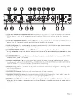
GATE/EXPANDER and COMPRESSOR
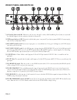
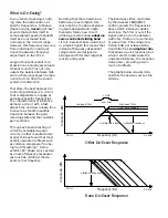
A noise GATE (sometimes referred to as a downward ex-
pander) extends the dynamic range of the signal by effectively
lowering the noise floor. All signals that are lower in level than
the setting on the GATE/EXPANDER THRESHOLD control
are attenutated at the selected ratio. When the RATIO switch is
set for 1.5:1, a 1 dB reduction in input level results in a 1.5 dB re-
duction in output level. For a 2:1 setting, a the same 1 dB input
level reduction results in a 2 dB reduction in output level.
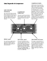
A good place to start with the GATE/EXPANDER is to
insure the BYPASS switch is
out
. Set the THRESHOLD control
to about -40 and the ratio to 1.5:1. Now apply the smallest signal
that you want to be processed by subsequent stages. An example
would be to talk softly into the MIC input. While talking,
notice that the THRESHOLD LED goes off and the GAIN
REDUCTION METER shows no gain reduction — this is
good. If the threshold LED stays on when talking softly, then
turn the THRESHOLD control CCW. The THRESHOLD
control is properly set when the lowest level signal to process
makes the THRESHOLD LED go
off,
and when that low
signal is removed the THRESHOLD LED comes back
on,
and
the GAIN REDUCTION meter shows gain reduction. Set the
GATE RATIO switch for the lowest ratio that provides the
amount of control desired. A setting of 1.5:1 allows for gentle
gain reduction below the threshold while a setting of 3:1 is more
detectable. For minimum effect set the GATE RATIO switch to
1.5:1 and set the THRESHOLD for -50.
The Compressor is familiar to anyone who has used Rane’s
darn cool DC 24 DYNAMIC CONTROLLER. While the
GATE/EXPANDER controls those signals lower in level than
your threshold setting, the COMPRESSOR controls those
signals above your COMPRESSOR THRESHOLD setting.
Once again, make sure that the BYPASS switch is
out
. Set the
COMPRESSOR THRESHOLD control to 20 and the COM-
PRESSOR RATIO to about 1.6:1. Now apply the largest signal
to be unaffected by the COMPRESSOR. This establishes the
highest signal level that will not be affected by the compressor
circuit. Adjust the THRESHOLD control CCW while talking
loudly or yelling. Stop adjusting the THRESHOLD control
when the THRESHOLD LED comes
on
. This is a good starting
point. A setting of 20 on the COMPRESSOR THRESHOLD
removes it’s effectiveness. The RATIO control sets the severity of
compression. A setting of 1:1 means no compressing (even if the
threshold LED is on), while a setting of 10:1 is very much like a
limiter, and will result in only a 1 dB increase in output level for
a 10 dB increase in input level.
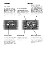
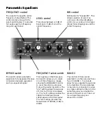
EQUALIZER
If you have used Rane’s PE 17 equalizer, then the EQ in the
VP 12 will look familiar. Adjust the FREQUENCY control
to the desired frequency, adjust the BW control for a range of
frequencies, and then adjust the LEVEL to either boost or cut.
For simple tone contours all you need to do is adjust the BW
control to a larger number like 2.0, and now you have affected a
broad range of frequencies. BW is measured in octaves, and each
doubling or halving of a frequency equals one octave. Adjust-
ing the FREQUENCY range switch selects multiples of the
FREQUENCY control, allowing each band to cover the full 20
Hz to 20 kHz range while maintaining resolution of the FRE-
QUENCY control.
The two bands are in series. This allows the two EQ sections
to add together. For a serious notch, for instance, adjust both sets
of controls to the same settings. Both LEVEL controls set at -15
dB deliver one serious -30 dB notch.
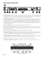
OUTPUT METER and LEVEL CONTROLS
The six segment output meter indicates the level coming
out of the VP 12. It is calibrated in dBu and is referenced to a
balanced output. If the output wiring is unbalanced, your actual
output will be 6 dB lower than that shown on the meter.
The LEVEL controls utilize a concentric potentiometer to
control two separate outputs or zones. The farthest out (inner)
knob controls the MAIN OUTPUT and the farthest in (outer)
knob controls the AUX OUTPUT.
Summary of Contents for VP 12
Page 1: ...VP 12 VOICE PROCESSOR...


