

Manual-
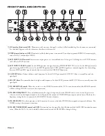
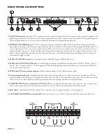
VP 12 CONNECTION
When connecting the VP 12 to other components in your
system
leave the power supply for last.
This gives you a chance to
make mistakes and correct them before any damage is done to
your fragile speakers and nerves.
The MIC input of the VP 12 is balanced and accepts a
standard XLR cable from the MIC of your choice. As with all
Rane products and AES standards, pin 2 is used for “hot” or “+”
polarity, pin 3 is “return” or “–” and pin 1 is chassis ground. If
you are not using PHANTOM POWER you may use either pin
1 or case for shield ground on the VP 12 input. However, if you
are using PHANTOM POWER, pin 1 must be shield grounded
to provide a complete electrical circuit.
The LINE/EXPAND input of the VP 12 is also balanced, as
a TRS jack or screw terminals. Choose one, these do not sum.
The tip is “+”, the ring is “–”, and the sleeve is chassis ground.
Unbalanced wiring such as a standard ¼" TS plug may also
work, but with possible compromises in level adjustments.
Outputs on the VP 12 are fully balanced. As expected, pin
2 is “hot” or “+”, pin 3 is “return” or “–” and pin 1 is chassis
ground. If unbalanced operation is required then simply connect
to the “+” and ground connections on the screw terminals, or
leave pin 3 unconnected on the XLR output connectors.
Refer to the RaneNote “Sound System Interconnection”
included with this manual for further information on wiring.
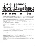
OPERATING INSTRUCTIONS
As with any piece of gear that includes this many features,
you can quite easily mess up the sound that you really meant to
improve. The features of the VP 12 are arranged in an order from
the factory, if followed, can make setting up properly an easy
operation. It is easier to start with all BYPASS switches in the
in
position, and add one process at a time. If a particular processing
section does nothing to improve the sound, BYPASS it!
INPUT SECTION
If you are using the MIC input only, set the front panel
switch to the MIC position. When setting up the MIC input
section, always take as much gain as possible right at the input.
Therefore, the highest level audio from the MIC INPUT should
just barely light the OL LED. We call this tickling the overload.
This may be illegal in your jurisdiction so please check your local
authorities. If only the LINE/EXPAND input is to be used, set
the front panel switch to LINE. Adjust the output level on the
previous device to just light the OL LED of the VP 12 when
receiving the largest signal you expect. Make sure that the previ-
ous device is not being overloaded by checking its OL sensor. To
use both the MIC input and LINE/EXPAND input, set up each
input as described above, then set the INPUT SELECT switch
to sum BOTH. Verify no OL condition exists with the loudest
signal fed to both inputs simultaneously.
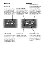
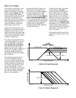
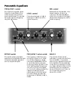
CUT FILTERS
Cut filters can improve the signal to noise performance of
your equipment. For example, rolling off some of the low end by
adjusting the LOW CUT FILTER gets rid of the noise caused by
wind blowing across your MIC. Or if previous equipment is less
than perfect when it comes to high frequency hiss, roll it off by
adjusting the HI CUT FILTER.
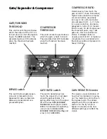
DE-ESSER
The DE-ESSER can be somewhat tricky to set up but here
are some helpful hints. The DE-ESSER can be set for multiple
people with moderate control, or if one person
sp
eak
s
with
s
ome
na
st
y
s
ibilan
c
e, the DE-ESSER offers even more control. To get
started, set the DE-ESSER controls for a frequency of 6 kHz,
RATIO of NORM, and a THRESHOLD of -30. Make sure the
BYPASS switch is
out
. Now speak the sibilance mantra, “Silly
Sally (or Sam depending on your gender bias) sells sea shells by
the sea shore”, into the mic. While saying this (over and over
until those listening make terrible threats) look at the front of the
VP 12 and monitor the DE-ESS THRESHOLD LED. The DE-
ESSER does nothing until that LED lights up. Notice the sound
quality coming out of your system when the LED is on. Your
mission is to adjust the controls so that sibilance is controlled,
but does not degrade the sound quality. All frequencies above the
setting on the FREQUENCY control are being level monitored.
A setting of 9 kHz is for very light DE-ESSING, 700 Hz is for
extreme DE-ESSING. The RATIO switch sets the amount of
band limiting for a given signal level above the threshold. The
THRESHOLD control establishes the signal level point that
must be exceeded before DE-ESSING occurs. A setting of 20
defeats the DE-ESSING function.
Summary of Contents for VP 12
Page 1: ...VP 12 VOICE PROCESSOR...


