


Manual-5
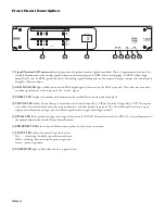
Versatile Output Port (VOP)
Eight open collector logic output pins are provided, each
capable of sinking 100 mA of current. The on-board REF voltage
of 12 VDC provides a maximum of 200 mA of current. Use an
external power supply (40 VDC maximum) if more current is
required, but be sure to connect the external supply’s ground to
the GND pin on the VOP.
RW 485 Port
The RW 485 port uses a simple, proprietary protocol to
communicate with Rane’s optional Smart Remotes (SR 2, SR 3,
SR 4). The details of this protocol are found in the SR Manuals,
available from Rane’s web site.
This port follows the electrical specification found in the
TIA/EIA-485 standard, with one exception: the recommended
termination impedance is neither implemented nor required,
since RW 485 uses a relatively slow baud rate (38,400 bps). In
fact, including the termination has proven to hinder the perfor-
mance of the RW 485 bus.
Five connection terminals are provided: a balanced pair of
data lines (A and B), a pair of power lines (±V), and a chassis
ground. All terminals should be connected to the corresponding
terminals of the Smart Remotes.
Up to eight remotes, each having a unique address, can be
connected to the RPM 44. Any mix of SR 2, SR 3 and SR4
remotes is possible, as is any combination of star or daisy chain
wiring configurations.
Control Connections
Versatile Input Port (VIP)
Eight logic input pins are provided, each capable of accept-
ing DC voltage between 0-5 VDC. VIP pins are used with
contact closure switches for Preset recall, or with potentiometers
for remote Level control. The functionality (Preset recall versus
control) of each pin is assignable as part of the Device Configu-
ration.
The maximum allowable voltage on any VIP pin is 5.3 VDC.
Use of twisted pair cable is recommended for better noise
immunity.
If an external device is used to generate a 0-5 V signal, con-
nect the ground of the external device to the GND pin of the
VIP.
Preset Recall Using Contact Closure Switches
The minimum “low” voltage required to detect a contact
closure and change Presets is 2.5 V. Since the internal pull up is
100 kΩ to +5 V, it is possible to calculate the maximum allow-
able cable length, provided the wire resistance per foot (or meter)
is known.
Example
:
To be safe, let’s allow a maximum of 80 kΩ worth of cable
resistance. This value keeps the voltage divider formed by the
100 kΩ internal resistance and 80 kΩ cable resistance from
dropping below 2.5 V.
(5 V * 100 kΩ) / (100 kΩ + 80 kΩ) = 2.777 V
If the cable resistance is 30 Ω per 1,000 feet
(1,000 feet / 30 Ω) * 80,000 Ω = 2,666,666 feet.
Thus, you can only use 2,666,666 feet (505 miles) of twisted
pair cable before the Preset recall functionality becomes inter-
mittent (assuming the cable is properly twisted and not run
through excessive magnetic or electric fields).
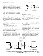
Remote Level Control Using Potentiometers
The VIP inherently prefers linear taper 10 kΩ potenti-
ometers, which provide a nice audio taper “feel” for the end
user. When used with suitable twisted pair wiring, the 10 kΩ
value also offers acceptable noise immunity and very long cable
lengths.
pin 1
GND
Contact
Closure
20 kΩ (linear)
Level Control
Potentiometer
VIP CONNECTION
(examples for VIP pin 1)
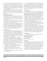
GND
REF
pin 1
1N4001
+12
pin 1
2 kΩ
+12
pin 1
(examples for VOP pin 1)
VOP CONNECTION
Light an LED
Relay Drive
100 mA coil
Crydom P/N D1225
current max
pin 1
+12
24 to
3
4
2
1
140 VAC
25 A max
Line Voltage Switching
NOTE: +12 VDC is available on the VOP. An external supply may be used as long as any VOP pin voltage never exeeds 40 VDC.
Examples shown are for 12 VDC only.