


Manual-2
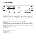
Front Panel Description
INPUT
1
2
3
4
OUTPUT
1
2
3
4
PRESET
RPM 44
A
B
A
B
Peak dBFS
-4
-12
-48
-4
-12
-48
-4
-12
-48
-4
-12
-48
AES3
AES3
LOCK
PROGRAMMABLE
MULTIPROCESSOR
VIP/VOP RW 485
ETHERNET STATUS POWER
1
2
3
4
5
6
7
8
1
Signal/Overload LED meters
indicate the presence of significant audio signal or overload. These 3-segment meters indicate the
available headroom once the analog signal has been converted to digital: -4 dBFS (red, near clipping), -12 dBFS (yellow, high
normal level), and -48 dBFS (green, low level). The analog signal level depends on the input and output settings and is displayed in
Drag Net’s Meter window.
2
AES3 LOCK LED
lights solidly when a valid AES3 digital signal is detected on the AES3 input jack. There does not need to be
an audio signal present at the input, only the “carrier” signal.
3
PRESET LED
displays the number of the most recently recalled Preset, numbered 0 through 24.
4
VIP/VOP LED
flashes when a change is detected on the Versatile Input Port (VIP) or Versatile Output Port (VOP). These ports
are used for direct electrical connections to potentiometers, switches or other logic ports. The Versatile Input Port accepts up to
eight contact closures or voltages; the Versatile Output Port drives eight loads (logic on/off).
5
RW 485 LED
flashes when a change in setting is detected on the RW 485 Remote Interface Port. RW 485 is a serial communica-
tions protocol primarily used for Rane’s Smart Remotes.
6
ETHERNET LED
flashes when an Ethernet data packet for this device is received.
7
STATUS LED
reflects the overall status of the unit:
Red - initializing (briefly) or possible internal error.
Yellow - working, but not currently processing audio.
Green - processing audio.
8
POWER LED
lights solidly when the unit is powered on.