


Manual-3
MM 42 Rear Panel
햲
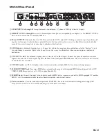
LINE INPUTS A through D:
Accept balanced or unbalanced, ¼" phone or XLR-style line-level inputs.
햳
DIRECT OUTS A through D:
are active balanced pass-throughs of corresponding Line Inputs. Use the DIRECT OUTS to
daisy-chain common mixes to multiple MM 42s.
햴
Main OUTPUTS
: Balanced, line-level, XLR connections for OUT 1 and OUT 2. Wiring convention is pin 2 positive, pin 3
negative (return), pin 1 is shield chassis ground. Refer to the
Sound System Interconnection
RaneNote (included with this
manual) for correct wiring when connecting to unbalanced destinations.
햵
SUB Output:
is balanced (tip-ring-sleeve). Connect to a subwoofer, amp/speaker combination or tactile “shakers” to add
low-end thump to ear mixes. Refer to the
Sound System Interconnection
RaneNote when connecting to an unbalanced
destination.
햶
CUE OUT 1 and 2:
is a balanced (tip-ring-sleeve), line-level Cue Bus Output. Connect to a spare transmitter or console
inputs to monitor the Cue Bus signal. Signal is identical to the front panel PHONES jacks. The Cue Out level is not affected
by the Phones Level control.
햷
CUE BUS jacks:
are RJ 12 (telephone-style) for interconnecting multiple MM 42s for cueing (soloing) purposes.
햸
MIDI OUT/THRU jack:
Incoming MIDI data is automatically merged with outgoing MIDI data and passed to the OUT/
THRU if MIDI Merge mode is set to ON (see page Manual-15).
햹
MIDI IN jack:
Connect this input to the output of another MIDI device (sequencer, controller, MIDI-equipped PC, another
MM 42, etc.) to accommodate data transfers, firmware updates, and external control.
햺
Power connector:
Uses the standard cord provided. The MM 42 has a universal internal switching power supply that
accepts 100 to 240 VAC at 50 to 60 Hz, allowing it to work in most countries.
ACN 001 345 482
THIS DEVICE COMPLIES WITH
PART 15 OF THE FCC RULES.
MADE IN U.S.A.
RANE CORP.
CUE BUS
50/60 Hz
20 WATTS
100-240V
OUT / THRU
IN
SUB
CUE OUT 2
OUT 2
CUE OUT 1
OUT 1
D
B
D
C
B
OUTS
C
A
DIRECT
A
MM 42
OUTPUTS
MIDI
LINE INPUTS
COMMERCIAL
AUDIO
EQUIPMENT
24TJ
R
C
US
LISTED
FOR CONTINUED
GROUNDING PROTECTION
DO NOT REMOVE SCREW
ALL BALANCED – TIP / PIN 2 = (+); SLEEVE = SIGNAL GROUND; PIN 1 = CHASSIS GROUND
ALL BALANCED
9
8
7
6
3
2
1
5
4