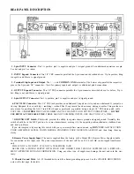

REAR PANEL DESCRIPTION
9. Chassis Ground Point.
A 6-32 threaded hole used for chassis grounding purposes. See the CHASSIS GROUNDING
note on the last page for details.
8. Remote Power Supply Input.
The unit is supplied from the factory with a Model RS 1 Remote Power Supply suitable
for connection to this input jack. The power requirements of the unit call for an 18-24 volt
AC
center-tapped transformer
only.
THIS IS NOT A DC INPUT. IT IS NOT A TELEPHONE JACK
NEVER USE A POWER SUPPLY WITH YOUR UNIT OTHER THAN THE ONE SUPPLIED OR A REPLACE-
MENT APPROVED BY RANE CORPORATION. Using any other type of supply may damage the unit and void the war-
ranty.
7.
GROUND LIFT Switch.
This switch provides the ability to separate chassis ground and signal ground. Normally, this
switch should be in the LIFT position. In some circumstances, moving it to the opposite position eliminates stubborn hum
and buzz problems.
If you arc tempted to try moving this switch with your power amplifiers turned on and up,
DON’T BE.
ALWAYS TURN
YOUR AMPLIFIER LEVELS DOWN BEFORE CHANGING YOUR GROUNDS AROUND and then bring them up
slowly.
6. PATCH I/O Connector.
This 1/4" TRS jack provides an unbalanced I (input) on its tip and an unbalanced O (output) on
its ring. Designed for use with tip = send/ring = return Effect Loop inserts found on many mixing consoles. This provides an
easy means for patching the GQ 15 into Effect Loops as painlessly as possible, using a single 1/4" TRS stereo patch cable.
CAUTION: USE
EITHER
THE PATCH I/O
OR
ANY OF THE INPUT AND OUTPUT CONNECTORS —
DO NOT
USE BOTH AT THE SAME TIME.
THESE ARE NOT SUMMING INPUTS. USE ONLY ONE AT A TIME.
5. 3-pin OUTPUT Connector.
Pin 2 is positive, pin 3 is negative and pin 1 is signal ground.
4. OUTPUT Expand Connector.
This 1/4" TRS connector parallels the 3-pin connector described above. As before, Tip is
hot, Ring is not and Sleeve is signal ground.
3. Terminal Strip Input and Output.
The +, –, and
COMMON GND
terminals of the barrier strip parallel the respective
pins in the 3-pin and 1/4" connectors. Used for primary inputs and outputs or additional patch connections.
2. INPUT Expand Connector.
This 1/4" TRS connector parallels the 3-pin connector described above. Tip
is
positive, Ring
is negative and Sleeve is signal ground.
1. 3-pin INPUT Connector.
Pin 2 is positive, pin 3 is negative and pin 1 is signal ground. For unbalanced operation, use pin
2 as hot and pin 1 as return.