background image

Manual-7

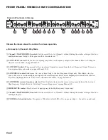
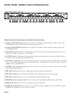
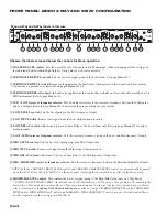
 HlGH-MID MUTE switch:

 Removes all signal from the High-Mid Output when pressed to the 

in 

position. 

This control is

disabled in 4-Way mode.

 HlGH-MID DELAY control:

 This control adds from 0 to 2 ms of time Delay to the High-Mid Output only. 

This control is

disabled in 4-Way mode.

 HlGH-MID/HIGH crossover frequency selector: 

This control sets the crossover Frequency between the High-Mid and

High Frequency Outputs.

 This control is disabled in 4-Way mode.

 HIGH LEVEL control:

 This controls the Level of signal to the High Output only.

 POWER switch and indicator:

 Two choices: on or off. If the power supply is plugged in, this yellow LED is lit, and the

POWER button is depressed, then the unit ready to operate.

See the Following Pages for Mono 4- or 5-Way Installation.

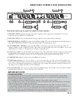
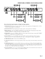
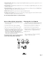
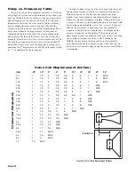
Mono 4-Way Switch Instructions

1. Be sure all power and audio is turned off. Remove the top

cover of the AC 23B.

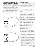
2. Locate the 4-WAY/5-WAY switch (see diagram).

3. Move the switch from the 5-WAY position to 4-WAY.

4. Replace the cover. The AC 23B is now set for Mono 4-

Way Mode. The HIGH-MID OUTPUT duplicates the MID
OUTPUT frequencies with a different low pass setting as
determined by the HIGH-MID / HIGH FREQUENCY
control, and is not normally recommended for use since the
tweeter crossover point will be inaccurate.

This operation must be reversed to operate the unit
in either Stereo 3-Way or Mono 5-Way Mode.

2W

3W

CHANNEL 2

STEREO

CHANNEL 1

STEREO

MONO

2W

3W

STEREO

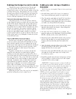
Monoing the Low Outputs

It is possible to mono the Low Frequency Outputs of the

AC 23B by an internal jumper. Set both Low Delays to “0”.

1. Remove the power cord and the AC 23B top cover.

2. Move the header to the J10 mono sum position.

3. Moving the header to the SHIP position puts the Low

Outputs back in stereo, as shipped from the factory.

4. Replace the cover.

The mono output is now at Channel 1 LOW OUT.
Channel 2’s LOW OUT is unused.

Summary of Contents for AC 23B

Page 1: ...it remains Pity See page Manual 6 for Mono 4 Way configuration In agreement with IEC and AES ANSI standards AC 22B wiring convention is pin 2 Positive pin 3 Negative return pin 1 chassis ground See t...

Page 2: ...ng Crossover Frequencies on page Manual 10 HIGH LEVEL control Sets the Level of signal going to the High frequency Output only Channel 2 MASTER LEVEL control Sets the overall Level of Channel 2 withou...

Page 3: ...still active and may be used as additional subwoofer outputs STEREO MONO switch Set this switch to the STEREO out position POWER input connector Use only a model RS 1 or other power supply approved by...

Page 4: ...MUTE switch Removes all signal from the Mid Frequency Output when pressed to the in position MID DELAY control Adds from 0 to 2 ms of time Delay to this Channel s Mid Output MID HIGH crossover frequen...

Page 5: ...equency amp and the CHANNEL 2 HIGH OUT to the right channel input of the high frequency amp MID OUTPUTS Connect the CHANNEL 1 MID OUT to the left channel of the mid frequency amp and the CHANNEL 2 MID...

Page 6: ...the Mid and High Mid Outputs NOTE Both the CHANNEL 1 HIGH LEVEL control and CHANNEL 2 MASTER LEVEL control are automatically bypassed when the AC 23B is switched to MONO on the back panel Adjusting th...

Page 7: ...turned off Remove the top cover of the AC 23B 2 Locate the 4 WAY 5 WAY switch see diagram 3 Move the switch from the 5 WAY position to 4 WAY 4 Replace the cover The AC 23B is now set for Mono 4 Way M...

Page 8: ...o the input of the subwoofer or bass bin amplifier LOW OUTPUT Connect the LOW OUT to the input of the low frequency mid bass amp MID OUTPUT Connect the MID OUT to the input of the mid frequency amplif...

Page 9: ...een Channels HlGH OUTPUT Connect the HIGH OUT to the input of the high frequency amplifier STEREO MONO switch Be sure this switch is in the STEREO out position Yes STEREO A Mono circuit is created whe...

Page 10: ...first into the realm of time delay and how to adjust it it might help to spend a moment here to re affirm why on earth this delay is really necessary For a short course on time delay Linkwitz Riley a...

Page 11: ...id driver at a comfortable volume 3 With a healthy but not uncomfortable volume of noise from the mid driver set the analyzer DISPLAY LEVEL control so the LED s corresponding to the high crossover fre...

Page 12: ...ophone until it is vertically midway between the mid and low drivers Repeat steps 2 through 5 using the crossover LEVEL control MUTE switch and next DELAY control You may start each series of steps 2...

Page 13: ...ill do not obtain a 3 dB reading you will have to physically move the high driver farther forward until the SPL meter reads 3 dB The amount of displacement corrections available from the delay depends...

Page 14: ...knob setting will then be the closest for your system For example if you have a two way system crossed over at 800 Hz with the compression driver voice coil located about 9 behind the woofer voice coi...

Page 15: ...d methods of setting the crossover output Levels Setting Levels Using a Realtime Analyzer NOTE If you are running two Channels tune up only one Channel at a time 1 Set all LEVEL controls on the crosso...

Page 16: ...se 1 Run pink noise into the crossover Inputs through the mixer or directly as is convenient 2 Make sure all crossover output LEVEL controls are turned all the way down and all amplifier level control...

Reviews: