background image

Trying Out the Instrument

R&S

®

SMCV100B

49

Getting Started 1432.7046.02 ─ 02

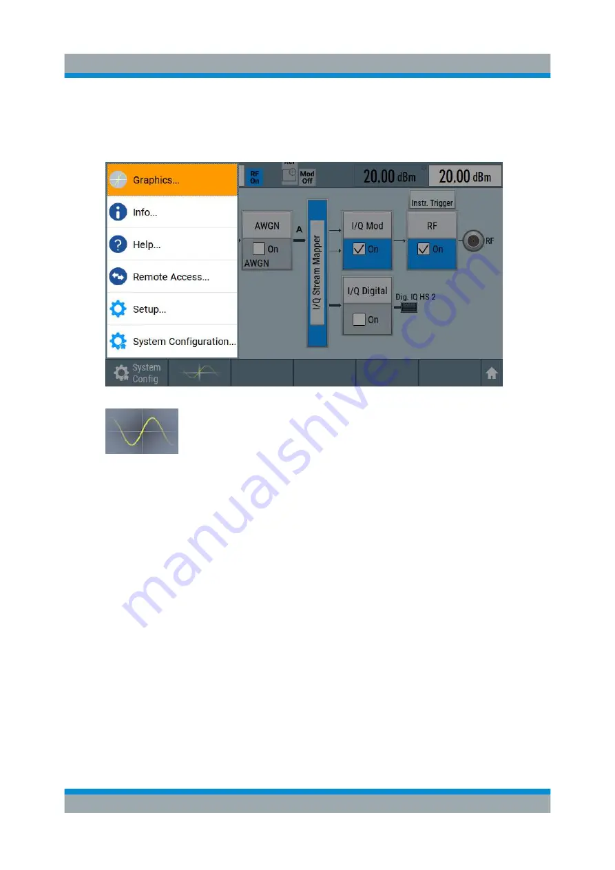
To access the graphical signal display functionality

► Perform one of the following:

● Select "Taskbar > System Configuration > Graphics".

● On the "Taskbar", tap the wave icon.

The "Graphics Configuration" dialog opens.

To visualize the signal

1. In the "Graphics Configuration" dialog, select "Mode > Constellation".

2. Select "Source > Baseband".

3. Select "Add" to enable signal display.

Verifying the Generated Signal with the Graphics Display

Summary of Contents for SMCVB-KB106

Page 1: ...100B Vector Signal Generator Getting Started Getting Started Version 02 1432704602 PÔ 2 Sie haben Fragen oder wünschen eine Beratung Angebotsanfrage unter 07121 51 50 50 oder über info datatec de Distributed by ...

Page 2: ...ww rohde schwarz com Subject to change Data without tolerance limits is not binding R S is a registered trademark of Rohde Schwarz GmbH Co KG Trade names are trademarks of the owners 1432 7046 02 Version 02 R S SMCV100B The following abbreviations are used throughout this manual R S SMCV100B is abbreviated as R S SMCV100B R S WinIQSIM2TM is abbreviated as R S WinIQSIM2 R S VISA is abbreviated as R...

Page 3: ...2 2 5 Printed Safety Instructions 12 2 6 Data Sheets and Brochures 12 2 7 Release Notes and Open Source Acknowledgment OSA 13 2 8 Application Notes Application Cards White Papers etc 13 3 Key Features 14 4 Preparing for Use 15 4 1 Lifting and Carrying 15 4 2 Unpacking and Checking 15 4 3 Choosing the Operating Site 15 4 4 Setting Up the R S SMCV100B 16 4 4 1 Placing the R S SMCV100B on a Bench Top...

Page 4: ...29 5 1 2 Keys 30 5 1 2 1 Utility Keys 30 5 1 2 2 On Standby 30 5 1 2 3 Function Keys 30 5 1 2 4 Editing Keys 31 5 1 2 5 Navigation Controls 31 Rotary Knob 31 5 1 3 Connectors 32 5 2 Rear Panel Tour 32 5 2 1 Connectors 33 6 Trying Out the Instrument 36 6 1 Generating an Unmodulated Carrier 37 6 2 Generating a Digitally Modulated Signal 39 6 3 Triggering the Instrument with an External Signal 41 6 4...

Page 5: ...61 7 7 I Q Modulator I Q Mod Block 62 7 8 RF RF Block 62 7 9 Applications Examples of the R S SMCV100B 62 8 Instrument Control 63 8 1 Possible Ways to Operate the Instrument 63 8 2 Means of Manual Interaction 64 8 3 Understanding the Display Information 64 8 3 1 Status Bar 65 8 3 2 Block Diagram 66 8 3 3 Taskbar 67 8 3 4 Additional Display Characteristics 68 8 4 Accessing the Functionality 70 8 5 ...

Page 6: ...Contents R S SMCV100B 6 Getting Started 1432 7046 02 02 8 8 Remote Operation over VNC 75 9 Contacting Customer Support 76 Index 77 ...

Page 7: ... page 7 The same information is provided in many languages as printed Safety Instructions The printed Safety Instructions are delivered with the product Throughout the documentation safety instructions are provided when you need to take care during setup or operation 1 1 Safety Instructions Products from the Rohde Schwarz group of companies are manufactured according to the highest technical stand...

Page 8: ... can operate the product up to an altitude of 2000 m above sea level The product is suitable for pollution degree 2 environ ments where nonconductive contamination can occur For more information on environmental conditions such as ambient temperature and humidity see the data sheet Setting up the product Always place the product on a stable flat and level surface with the bottom of the product fac...

Page 9: ...mplies with country specific safety requirements Only insert the plug into an outlet with protective conductor terminal Only use intact cables and route them carefully so that they cannot be dam aged Check the power cables regularly to ensure that they are undamaged Also ensure that nobody can trip over loose cables If the product needs an external power supply use the power supply that is deliver...

Page 10: ...tric shock should an electric problem occur 1 2 Labels on R S SMCV100B Labels on the casing inform about Personal safety see Connecting to power on page 9 Product and environment safety see Table 1 1 Identification of the product see the serial number on the rear panel Table 1 1 Labels regarding R S SMCV100B and environment safety Labeling in line with EN 50419 for disposal of electrical and elect...

Page 11: ...e software options are provided for download Base unit manual Contains the description of all instrument modes and functions It also pro vides an introduction to remote control a complete description of the remote control commands with programming examples and information on mainte nance instrument interfaces and error messages Includes the contents of the getting started manual Software option ma...

Page 12: ...4 Instrument Security Procedures Deals with security issues when working with the R S SMCV100B in secure areas It is available for download on the Internet 2 5 Printed Safety Instructions Provides safety information in many languages The printed document is deliv ered with the product 2 6 Data Sheets and Brochures The data sheet contains the technical specifications of the R S SMCV100B It also lis...

Page 13: ...scribe the firmware installation The open source acknowledgment document provides verbatim license texts of the used open source software See www rohde schwarz com firmware smcv100b 2 8 Application Notes Application Cards White Papers etc These documents deal with special applications or background information on particular topics See www rohde schwarz com application smcv100b Application Notes Ap...

Page 14: ...ernal baseband Powerful internal baseband generator with internal broadcast real time coder Custom Digital Modulation and internal baseband signal generation with ARB Support of terrestrial satellite and audio broadcast standards such as ATSC 3 0 ATSC M H DTMB DVB T2 DVB T ISDB T ISDB TSB T DMB DAB DVB S2 DVB S DRM DRM Audio AM FM RDS RDBS DARC Support of digital standard waveforms such as 5G NR L...

Page 15: ...aterial Use it to protect the control elements and connectors when transporting or shipping the R S SMCV100B later See also chapter Transporting in the user manual 3 Using the delivery notes check the equipment for completeness 4 Check the equipment for damage If the delivery is incomplete or equipment is damaged contact Rohde Schwarz 4 3 Choosing the Operating Site Specific operating conditions e...

Page 16: ...le for class B environments If class A equipment causes radio disturbances take appropriate measures to eliminate them 4 4 Setting Up the R S SMCV100B See also Setting up the product on page 8 Intended use on page 7 4 4 1 Placing the R S SMCV100B on a Bench Top To place the product on a bench top 1 Place the product on a stable flat and level surface Ensure that the surface can support the weight ...

Page 17: ...or other products 4 4 2 Mounting the R S SMCV100B in a Rack To prepare the rack 1 Observe the requirements and instructions in Setting up the product on page 8 2 NOTICE Insufficient airflow can cause overheating and damage the product Design and implement an efficient ventilation concept for the rack To mount the R S SMCV100B in a rack 1 Use an adapter kit that fits the dimensions of the R S SMCV1...

Page 18: ...the R S SMCV100B Follow the instructions provided with the adapter kit 4 5 Important Aspects for Test Setup Cable selection and electromagnetic interference EMI Electromagnetic interference EMI can affect the measurement results To suppress electromagnetic radiation during operation Use high quality shielded cables especially for the following connector types BNC Double shielded BNC cables USB Dou...

Page 19: ...ep the signal levels within the specified ranges to avoid damage to the R S SMCV100B and connec ted devices 4 6 Connecting to Power For safety information see Connecting to power on page 9 1 Plug the AC power cable into the AC power connector on the rear panel of the instrument Only use the AC power cable delivered with the R S SMCV100B 2 Plug the AC power cable into a power outlet with ground con...

Page 20: ...w to connect a monitor for direct operation of the R S SMCV100B You can skip the following procedure if you only operate the R S SMCV100B remotely The connector is located on the rear panel Connect the monitor to the DVI D socket You can connect the following types of monitor sockets DVI D Connect it to the DVI D socket DVI A not supported DVI I not supported HDMI You need an adapter Use a passive...

Page 21: ...cur rent into the 5 V power supply of the USB interface and thus damage the R S SMCV100B Ensure that there is no connection between the positive pole of the power supply and the 5 V power pin of the USB interface VBUS 2 Connect the USB storage device to any of the USB connectors To connect a keyboard Connect the keyboard to any of the USB connectors When connected the R S SMCV100B detects the keyb...

Page 22: ...a Carefully align the connector of the cable and the RF 50 Ω connector along a common axis b Mate the connectors along the common axis until the male pin of the con nector of the cable engages with the female socket of the RF 50 Ω con nector Preventing RF output switch off NOTICE If you set a too high output level the reverse power can exceed a limit forcing the R S SMCV100B to switch off the RF o...

Page 23: ...ted on the rear panel To connect to Dig IQ HS x interface 1 For connection use the QSFP cable R S DIGIQ HS See Cable selection and electromagnetic interference EMI on page 18 2 Hold the QSFP plug of the cable by its panes 3 Turn the QSFP cable so that the release tab shows upwards 4 Insert and push the QSFP plug into the QSFP cage To disconnect from Dig IQ HS x interface 1 NOTICE If you pull the c...

Page 24: ...SFP cage 2 SFP connector The connector is located on the rear panel To connect to IP Data interface 1 For connection use an SFP to RJ 45 adapter and an RJ 45 cable See Cable selection and electromagnetic interference EMI on page 18 Figure 4 2 Connecting to the IP Data interface 1 SFP socket of the IP Data connector 2 SFP to RJ 45 adapter 2a Bracket for mounting and releasing the adapter 3 RJ 45 ca...

Page 25: ...ble into the RJ 45 socket of the adapter To disconnect from IP Data interface 1 Unplug the RJ 45 cable 2 Open the release bracket 3 Carefully pull the SFP to RJ 45 adapter out of the SFP socket of the IP Data interface Use the IP Data interface as input of external coding IP data for broadcast base band signals See also chapter Local IP Data Network Settings in the corresponding broad cast standar...

Page 26: ...th the default settings When restarting the instrument the settings depend on the instru ment configuration before shut down See the chapter Saving and Recalling Instrument Settings in the user man ual When the instrument is switched on it automatically monitors main functions You can query erroneous functions In addition to automatic monitoring you can per form maintenance tasks See Chapter Query...

Page 27: ...state 1 NOTICE Risk of data loss If you disconnect the product from power when it is in the ready state you can lose settings and data Shut it down first Set the toggle switch on the power supply to position 0 The LED of the On Standby key is switched off 2 Disconnect the R S SMCV100B from the power source Switching On or Off ...

Page 28: ... data sheet The meanings of the labels on the R S SMCV100B are described in Chapter 1 2 Labels on R S SMCV100B on page 10 5 1 Front Panel Tour This section provides an overview of the control elements and connectors of the front panel of the R S SMCV100B On the rear panel you find all further connec tors of the unit 7 2 3 5 6 4 1 Figure 5 1 Front panel view 1 Touchscreen see Chapter 5 1 1 Touchscr...

Page 29: ...n and allows you to quickly reconfigure the signal flow The screen is touch sensitive offering an alternative means of user interaction for quick and easy handling of the instrument Figure 5 2 Touchscreen elements 1 Status bar frequency and level display 2 Block diagram 3 Taskbar softkey bar Any user interface elements that react to a click by a mouse pointer also react to a tap on the screen and ...

Page 30: ...eneral Instrument Functions in the user manual Table 5 1 Utility keys Utility key Assigned functions Preset Sets the instrument to a defined state Save Rcl Saves and loads instrument setting Accesses the file manager Help Displays context sensitive help text 5 1 2 2 On Standby The On Standby key switches the instrument from the standby to the ready state or vice versa The LED below the On Standby ...

Page 31: ... Description Esc key Closes all kinds of dialog boxes if the edit mode is not active Quits the edit mode if the edit mode is active In dialog boxes that contain a Cancel button it activates that button For Edit dialog boxes the following mechanism is used If data entry has been started it retains the original value and closes the dialog box If data entry has not been started or has been completed ...

Page 32: ...universal serial bus 2 0 connector of type A host USB on the front panel You can connect for example a keyboard a mouse or a USB memory stick Further USB connectors of type A are available on the rear panel How to Chapter 4 9 Connecting USB Devices on page 21 RF 50 Ω N female connector for output of the RF signal How to Chapter 4 10 Connecting to RF 50 Ω on page 22 5 2 Rear Panel Tour This section...

Page 33: ... on page 34 7 User x connectors User x on page 34 8 IP Data connector see IP Data on page 34 9 Dig IQ HS x connector see Dig IQ HS x on page 35 5 2 1 Connectors AC power supply connector and switch Mains power switch for performing the following tasks Connecting the internal power supply to the power source Disconnecting the internal power supply from the power source How to Chapter 4 6 Connecting...

Page 34: ...1 Connecting to Ref In Ref Out on page 22 User x BNC multipurpose connectors for defining input signals and output signals Table 5 4 lists the signals assigned to the User x connectors in the default instrument state Table 5 4 Default configuration of the User x connectors User connector Direction Default assigned signal 1 Output Baseband Marker 1 2 Input Global Clock A dedicated LED indicates the...

Page 35: ...signation input output and the required option For more information see data sheet Table 5 5 Overview of Dig IQ HS x interfaces and required options Interface Designation Required option Dig IQ HS 1 BB Input R S SMCVB K19 digital baseband interface Dig IQ HS 2 I Q Digital Out The interface is a QSFP Quad Small Form factor Pluggable module It sup ports max bandwidth of up to 50 Gsample s with optic...

Page 36: ...ou do not need any additional signal source More complex signal generation tasks however require an instrument equipped with additional options and or external signals Each task description lists its prerequisites The screenshots in this description show a fully equipped instrument Con sider that the block diagram displayed on your particular instrument can dif fer from the one used in the example...

Page 37: ...t panel press the Preset key to start out in a defined instrument configuration 2 Set the frequency a On the Status Bar tap the Frequency field b On the on screen keypad enter 1 955 and press the GHz key The on screen keypad closes and the frequency value is displayed 3 On the Status Bar tap the Level field and enter the level in the same way 4 Select Block Diagram RF Block On to enable the output...

Page 38: ...ignal is output at the RF 50 Ω connector at the front panel of the R S SMCV100B Connect RF 50 Ω of the R S SMCV100B to a signal analyzer for exam ple R S FSW to display the generated signal Figure 6 2 Simplified test setup For the required settings of the signal analyzer refer to its user manual or its online help Generating an Unmodulated Carrier ...

Page 39: ... Option custom digital modulation R S SMCVB K199 The initial situation is not the instrument s preset state but rather the configuration described in Chapter 6 1 Generating an Unmodulated Carrier on page 37 1 In the block diagram select Baseband and navigate to the section Misc Custom Digital Mod The Custom Digital Modulation dialog opens 2 In the Custom Digital Modulation dialog select General Se...

Page 40: ...2 The instrument activates automatically I Q Mod uses the internal trigger and clock signals and generates a WCDMA 3GPP signal modulated with a QPSK 45 offset modulation Figure 6 3 Block diagram Generating a digitally modulated signal Generating a Digitally Modulated Signal ...

Page 41: ...ustom digital modulation R S SMCVB K199 As a rule whenever a test setup requires two or more devices provide them with a common reference frequency Some test setups require control of the signal generation start and an exact generation start time determined by a defined trig ger event For example by triggering the instrument internally or externally from the DUT The example below illustrates the g...

Page 42: ...instrument and the external trigger source See To connect the instrument and the external trigger source on page 45 To verify the current connector configuration The R S SMCV100B is equipped with multipurpose bi directional User connec tors Because the signal direction input or output and the signal mapping are configurable we recommend that you check the current configuration before cabling or fu...

Page 43: ...e 6 5 Signal mapping to the global connectors The Global Connectors dialog displays the current connectors configuration The settings are configurable but in this example we use the default mapping 3 Alternatively select Block Diagram Baseband Misc Custom Digital Mod select the Trigger In tab and select Global Connector Settings In the current mapping the two global connectors User x on the rear p...

Page 44: ...also indicates the selected connector To reconfigure the trigger settings We assume that the instrument is configured as described in Chapter 6 2 Gen erating a Digitally Modulated Signal on page 39 and the default connector map ping is maintained see Figure 6 5 1 In the block diagram select Baseband Misc Custom Digital Mod Trigger In 2 Select the following settings a Mode Armed Auto b Source Exter...

Page 45: ...t the input connector User 2 The Trigger Marker Clock status LEDs in the block diagram confirm that an external trigger signal is selected the signal generation is however stopped To connect the instrument and the external trigger source 1 Use a suitable cable to connect the external trigger source to the User 2 connector of the R S SMCV100B See Figure 6 6 Triggering the Instrument with an Externa...

Page 46: ...rigger source the DUT can also send for example a frame trigger signal to the R S SMCV100B The R S SMCV100B acts still as the signal source 2 Use suitable cables to connect to RF 50 Ω and Ref In connectors of the R S SMCV100B to the signal analyzer or the DUT The R S FSW supplies the 10 MHz external reference signal Upon the receiving of an external trigger event the R S SMCV100B starts the signal...

Page 47: ...on as in Prerequisites on page 36 Option custom digital modulation R S SMCVB K199 This example extends further the configurations performed in Chapter 6 2 Gen erating a Digitally Modulated Signal on page 39 We assume a default connector mapping see Figure 6 5 This test setup requires one oscilloscope like the R S RTO as additional equip ment 1 In the block diagram select Block Diagram Baseband Mis...

Page 48: ...ck the spectra of the configured signals before you enable the RF output of the instrument The R S SMCV100B has a minimum configura tion as in Prerequisites on page 36 The R S SMCV100B provides a build in function to represent the generated sig nal on a graphical signal display We demonstrate this feature by showing the characteristics at one particular point of the signal processing chain You can...

Page 49: ...f the following Select Taskbar System Configuration Graphics On the Taskbar tap the wave icon The Graphics Configuration dialog opens To visualize the signal 1 In the Graphics Configuration dialog select Mode Constellation 2 Select Source Baseband 3 Select Add to enable signal display Verifying the Generated Signal with the Graphics Display ...

Page 50: ...u can verify that Channel 0 graphic is visible in the table A new thumbnail minimized view indicating the active diagram appears in the Taskbar 4 Press the thumbnail graphic The graphic enlarges and the diagram is displayed in a normal size Verifying the Generated Signal with the Graphics Display ...

Page 51: ... pinching for magni fying images on your cellphone 6 In the Constellation Diagram dialog select Configure to return to the Graphics Configuration dialog Close the Graphics Configuration dialog This action has no effect on the configured graphics but on the dialog itself The block diagram displays the current signal routing It indicates that fre quency and power offsets are enabled and displays the...

Page 52: ...ment settings to a file To save the instrument settings to a file We assume a test configuration as described in Chapter 6 4 Enabling and Con figuring a Marker Signal on page 47 1 Press the Save Rcl key on the front panel 2 In the Save Recall dialog box select Operation Mode Save Tap the Filename use the on screen keyboard and enter MyTestSignal Saving and Recalling Settings ...

Page 53: ...ser To load saved instrument settings You can restore the settings to the instrument at any time using the settings file 1 Press the Preset button to restore the default instrument settings 2 Press the Save Rcl key 3 In the Save Recall dialog select Recall operation Navigate to the directory of the saved file Select the MyTestSignal file Saving and Recalling Settings ...

Page 54: ...alues different to their preset values After loading saved instrument setting visualize all parameters that have been changed from their default state 1 In the block diagram open the context sensitive menu a Imitate a right click b Tap and hold on an empty space in the block diagram for about one sec ond 2 In the context sensitive menu select Mark All Parameters Changed from Pre set All changed pa...

Page 55: ... T2 or ATSC3 0 to name a few This example uses the digital broadcast standard DAB You can access and interact with the instrument and experience the advantages provided by the additional options Prerequisites Minimum configuration as in Prerequisites on page 36 Option Enable broadcast standard R S SMCVB K519 Option DAB T DMB R S SMCVB K156 To generate a DAB test signal 1 On the R S SMCV100B front ...

Page 56: ...ss to further functions and dialogs The more complex the digital standard itself is the more comprehensive the further dialog and tab structure 3 In the Input Signal tab select Source Test Signal The test signal is a signal with audio content Tip On the front panel press the Help key to retrieve detailed information on the current settings and on the contents of the predefined files 4 In the T DMB...

Page 57: ...F On RF On The instrument generates a DAB test signal with the set frequency and level With these first steps you have gained an impression of the provided func tionality For a comprehensive description of the full range of capabilities refer to the user manual DAB Digital Standard for R S SMCV100B Generating a DAB Signal ...

Page 58: ...and section of the R S SMCV100B is fully digital It contains the hardware for generating and processing I Q signals in realtime or generating signals with an arbitrary waveform generator 7 2 Signal Flow at a Glance The R S SMCV100B is equipped with a large touchscreen that displays a block diagram The block diagram represents the signal flow and the general stages the signal generation goes throug...

Page 59: ...talled options and the displayed set tings The Table 7 1 is an excerpt of the available options and lists only the options required to display a functional block in the block diagram The information assumes R S SMCV100B minimum configuration comprising base unit and fre quency option R S SMCVB B103 For exact information on the available options and on the minimum requirements and the interdependen...

Page 60: ...ules for real time signal generation Custom Digital Modulation requires R S SMCVB K199 and an arbitrary waveform generator ARB The available digital standards Generation of digital signals in accordance with the supported standards requires additional software options For example option R S SMCVB K162 generates signals according to the ATSC 3 0 standard The baseband offsets function Signals from t...

Page 61: ...al I Q signals are further processed in the baseband section The baseband offsets function The external and internal baseband signals can be shifted in frequency and phase The I Q Digital block is the access point to the settings of the digital I Q output signals 7 5 Additional White Gaussian Noise AWGN Block The AWGN block is displayed only in instruments equipped with the option R S SMCVB K62 Th...

Page 62: ...the access point to RF frequency and level settings and the reference frequency user correction etc The list and sweep modes 7 9 Applications Examples of the R S SMCV100B The R S SMCV100B can be optimally adapted to the requirements of different applications Generation of digitally modulated signals using The internal baseband generator The externally applied digital baseband signals Generation of...

Page 63: ... and rotary knob or an optional mouse and or keyboard The following description shows how to operate the instrument manually Remote control Create programs to automatize repeating settings tests and measurements The instrument is connected to a computer running the program This way of operation is described in the user manual chapter Network and Remote Control Operation Remote operation from a com...

Page 64: ...ion keys and rotary knob The front panel provides nearly all functions and controls to operate the instru ment in the classic way without touchscreen Optional mouse and or keyboard These devices work like known from PCs The navigation keys on the front panel correspond to the keys on the keyboard This manual describes the manual interaction with the instrument via the touch screen It mentions the ...

Page 65: ... 68 8 3 1 Status Bar The status bar at the top of the screen indicates the RF frequency and the level of the output signal provided to the DUT You can set both parameters directly here 1 Frequency display 2 Status buttons 3 Level display The status buttons indicate key parameters that are set for the output signal Most of the status buttons are virtual keys you can use to open a corresponding menu...

Page 66: ...ital Starting from left up to the I Q Stream Mapper you can see the functional blocks provided in the baseband domain After the stream mapper the analog section contains the digital to analog conversion and modulation to RF Legend Item Description 1 Status indicator Indicates whether the signal is running or waiting for a trigger 2 Functional block Represents a basic task in signal generation The ...

Page 67: ...7 Connector icons Represent the interfaces for signal input and output RF signal connector output 7a Icons vary depending on the frequency Digital I Q HS signal connector input and output 7b 7c 8 3 3 Taskbar The Taskbar contains labeled softkeys and minimized views thumbnails of active graphics and dialogs Initially it shows the permanently assigned softkeys The softkey with the sine wave denotes ...

Page 68: ... selection list with the remaining active dialogs and the Diagram function 8 3 4 Additional Display Characteristics The following section provides a short insight on the indication of the screen in general and significant elements that you see under specific operating modes in dialogs or settings Appearance of active elements Active elements like On Off switches state buttons have a blue back grou...

Page 69: ...ndicators or the set value of a key parameter 1 Status indicators 2 Key parameter values Scroll bar handle An arrow icon that appears when you touch a scroll bar helps you to scroll in a dialog or list Context sensitive menus Within the entire screen display including single parameters you can access context sensitive menus that provide some additional functions Understanding the Display Informati...

Page 70: ...he status bar in the touchscreen Displayed setting on the touchscreen that means block diagram and all set tings available in dialogs To open a dialog box Perform one of the following actions Tap the required block and then the menu entry Tap the minimized view thumbnail on the taskbar Some of the utility keys access a dedicated dialog too To minimize a dialog box To return to the block diagram ta...

Page 71: ... Data Some parameters have their own key on the front panel For data input in dialog boxes the instrument provides on screen keypads for entering numeric and alphanumeric values Thus you can always set the param eters via the touchscreen the front panel or an external keyboard Correcting an entry 1 Using the arrow keys move the cursor to the right of the entry you want to delete 2 On the on screen...

Page 72: ...f you edit numeric data in tables the entry field must be in edit mode Press the rotary knob to activate the edit mode 8 5 2 Entering Alphanumeric Parameters If a field requires alphanumeric input you can use the on screen keyboard to enter letters and special characters 8 5 3 Undo and Redo Actions Accessed via the context sensitive menus Undo allows you to restore one or more actions on the instr...

Page 73: ... a help topic perform one of the following a Tap and hold the parameter for which you need information and tap Help in the context menu b Tap the parameter and press the Help key The Help dialog opens You can browse the help for further information Contents of the help dialog box The help dialog box covers two main areas Contents contains a table of help contents Topic contains a specific help top...

Page 74: ... This function scrolls back all steps you have performed before 5 Use the scroll bars to shift the visible section of content shown 6 To maximize the Topics area tap the Hide Contents Tree button to hide the contents tree Using the index 1 Select the Index button 2 Enter the first characters of the topic you are interested in The entries starting with these characters are displayed 3 Tap on the in...

Page 75: ...ion the instrument screen contents are displayed on the remote com puter and VNC provides access to all applications files and network resources of the instrument Thus remote operation of the instrument is possible Instrument control from a remote computer To access the basic utility functions of the R S SMCV100B perform a right mouse click the block diagram and select Key Emulation A key panel to...

Page 76: ...oduct contact our customer support center A team of highly qualified engineers provides support and works with you to find a solution to your query on any aspect of the operation program ming or applications of Rohde Schwarz products Contact information Contact our customer support center at www rohde schwarz com support or fol low this QR code Figure 9 1 QR code to the Rohde Schwarz support page ...

Page 77: ...33 DVI D 33 High speed digital IQ 35 IP data 34 LAN 34 Ref In 34 Ref Out 34 RF 32 USB 32 34 USER 34 Context sensitive menu 68 Custom digital modulation 60 Customer support 76 D Data entry 71 Data sheets 12 Dialog boxes 70 Digital standard 60 Display Active elements 68 Block diagram 66 Context sensitive menu 68 Info line 68 Information 64 On screen keypad 68 Status bar 65 Tab labels 68 Taskbar 67 D...

Page 78: ...n 64 Mounting in a rack 17 Mouse Usage 64 N Numeric data entry 71 Numeric parameters 72 O On screen keyboard 72 On screen keypad 68 Open source acknowledgment OSA 13 Operating site Choosing 15 Setting up the instrument 16 Operation Manual 64 Options see user manual 60 Output connector 32 34 35 P Parameters Entering 72 Placing on a bench top 16 Power Connecting the instrument 19 Power on Key 30 Pow...

Page 79: ...ry 71 Tooltips Show 73 Touchscreen Compared with mouse 64 Overview 29 Usage 64 U Unpacking the instrument 15 User manual 11 Utility keys Details see user manual 30 Overview 30 V VNC Using in a LAN 75 W White papers 13 Sie haben Fragen oder wünschen eine Beratung Angebotsanfrage unter 07121 51 50 50 oder über info datatec de Distributed by ...

Reviews: