GUI reference
R&S
®
ZNA
763
User Manual 1178.6462.02 ─ 20
If the active trace is a reflection trace S
ii
, the analyzer firmware assumes that the DUT
is connected to port
p=i
. Otherwise it assumes that the DUT is connected to port
p
=2.
When activating "Distance to Fault", the analyzer firmware
●
sets S
pp
as measured quantity of the active trace
●
enables additional controls on the "Distance to Fault" tab
●
appends the selected cable type to the trace label (see
●
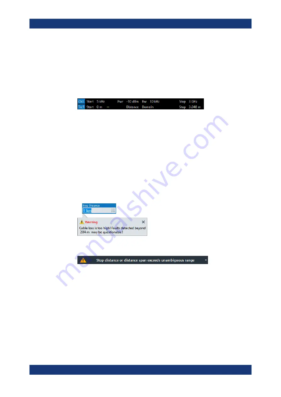
displays an additional "Distance Domain" trace info line below the channel line
Note that all info lines (channel info, trace info,"Distance Domain" trace info) allow
quick access to related parameters via specific context menus:
"Distance to Fault" can also be enabled/disabled via the context menu of the trace
label.
Remote command:
CALCulate<Chn>:TRANsform:DTFault:STATe
Start Distance / Stop Distance
Define the distance window for the Distance to Fault measurement. "Start Distance"
and "Stop Distance" correspond to the left and right edge of the diagram area and are
displayed in the "Distance Domain" trace info line.
Note:
●
If the "Stop Distance" is so high that for the selected
the signal reflected
at "far away discontinuities" would be too small, a warning tooltip is displayed:
●
If the "Stop Distance" exceeds the unambiguous range (for the given frequency
span and number of sweep points), a warning is displayed in the instrument status
bar:
function to adjust the number of sweep points so
that the impulse response becomes unambiguous in the configured distance win-
dow.
Remote command:
CALCulate<Chn>:TRANsform:DTFault:STARt
CALCulate<Chn>:TRANsform:DTFault:STOP
CALCulate<Chn>:TRANsform:DTFault:CENTer
CALCulate<Chn>:TRANsform:DTFault:SPAN
Auto Number of Points
Selects the minimum number of sweep points that are required to provide an unambig-
uous display of fault locations for the active Distance to Fault trace.
Applic softtool


