background image

OM-8000 & 9000W SERIES PREP TABLES

For more information on preventive maintenance, consult your local service 
company or CFESA member.  Most repair companies offer this service at very 
reasonable rates to allow you the time you need to run your business along with 
the peace of mind that all your equipment will last throughout its expected life.  
These services often offer guarantees as well as the flexibility in scheduling or 
maintenance for your convenience. For a complete listing of current Unified Brands 
ASA please visit www.unifiedbrands.net.
Unified Brands believes strongly in the products it manufactures and backs those 
products with one of the best warranties in the industry.  We believe with the 
proper maintenance and use, you will realize a profitable return on your investment 
and years of satisfied service.

REPLACEMENT PARTS

To order parts, contact your Authorized Service Agent. Supply the model 
designation, serial number, part description, part number, quantity, and when 
applicable, voltage and phase.

CONTACT US

If you have questions pertaining to the content in this manual, contact Unified 
Brands at 888-994-7636 or [email protected].

TROUBLESHOOTING

This unit is designed to operate smoothly and efficiently if properly maintained. 
However, the following is a list of checks to make in the event of a problem. Wir-
ing diagrams are found at the end of this manual. When in doubt, turn unit off 
and contact service at 888-994-7636 or [email protected].

SYMPTOM

POSSIBLE CAUSE

PROCEDURE

Unit does not run

No power to unit

Plug in unit

Control in OFF position

Turn controller on

Faulty control

Call for service at 888-994-
7636

Unit too cold

Incorrect set point

Adjust control set point

Unit too warm

Door / drawer ajar

Ensure door / drawer is fully 
closed

Gasket torn or out of place

Inspect the gasket for wear 
and position

Incorrect set point

Adjust control set point

Warm product introduced 
to cabinet

Pre-chill product 37ºF

Ice on the coil

Initiate manual defrost

Unit noisy

Ice on the coil

Initiate manual defrost

Unit does not defrost Excessive ice on the coil

Initiate manual defrost

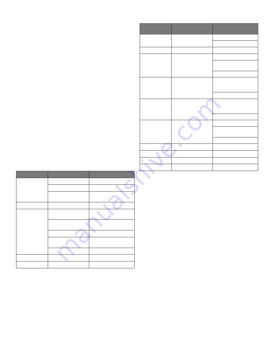
DANFOSS CONTROLLER CODES

DISPLAYED 

ALARM CODE

ALARM

ACTION

Hi

High Temperature Alarm

Inspect door/drawer sealing

Contact service

Lo

Low Temperature Alarm

Contact service

CON

Condenser Temperature 
High Limit 

Clean condenser coil

Inspect coil for any objects 
obstruction hindering airflow 

Contact service

uHi

Line Voltage Too High

Verify voltage of power source, 
to be performed by qualified 
technician

Contact service

uLi

Line Voltage Too Low

Verify voltage of power source, 
to be performed by qualified 
technician

Contact service

LEA

Continuous Compressor 
Runtime  

Inspect door/drawer sealing

Inspect condenser coil, clean if 
necessary

Contact service

E01

S1 Sensor Failure 

Contact service

E02

S2 Sensor Failure 

Contact service

E03

S3 Sensor Failure 

Contact service

E04

S4 Sensor Failure 

Contact service

Summary of Contents for 9000W-290 Series

Page 1: ...estions 888 994 7636 RETAIN THIS MANUAL FOR FUTURE REFERENCE NOTICE Due to a continuous program of product improvement Unified Brands reserves the right to make changes in design and specifications wi...

Page 2: ...necessary when ordering replacement parts or requesting warranty service 9 Allow your unit to operate for approximately 45 minutes before putting in food in the rail Allow 2 hours for base of the unit...

Page 3: ...MAKE CHANGES OF 2 DEGREE INCREMENTS AT A TIME ALLOW FOR THE UNIT TO OPERATE 24 HOURS BETWEEN ADJUSTMENTS IF THE 2 DEGREE ADJUSTMENT IS NOT ENOUGH ANOTHER ADJUSTMENT CAN BE MADE IF THE SETTINGS NEED TO...

Page 4: ...a monthly basis Condenser coils are a critical component in the life of the compressor and must remain clean to assure proper air flow and heat transfer Failure to maintain this heat transfer will af...

Page 5: ...at the end of this manual When in doubt turn unit off and contact service at 888 994 7636 or tsrandell unifiedbrands net SYMPTOM POSSIBLE CAUSE PROCEDURE Unit does not run No power to unit Plug in uni...

Page 6: ...ND REPAIR Leak check an R 290 system the same way you would an R 134a or R 404A system with the following exceptions 1 Do not use a Halid leak detector on a R290 system 2 Electronic leak detector must...

Page 7: ...MED RAIL DBL COMP SYSM X X X X X 1 RP CNT1806 CONTOLLER PROGRAMMED BASE SGL COMPR SYSM X X X X X X X 1 RP CNT1807 CONTOLLER PROGRAMMED BASE DBL COMP SYSM X X X X 2 RF CNT1602 SENSOR COIL X X X X X X X...

Page 8: ...UNIT X X X X X 5A RP SHD1806 SHROUD COND UNIT X 5B RP SHD1807 SHROUD COND UNIT X X X 5C RP SHD1808 SHROUD COND UNIT X 6 RP PNL1803 COVER ACCCESS SIDE CMPR L OR R X X X X 7 HD SHL180 SHELF 22 X 25 X X...

Page 9: ...MAGNET X X X 4 HD BMP034 BUMPER RUBBER X X X 5 RP SHD1814 SHROUD COND UNIT X 5A RP SHD1815 SHROUD COND UNIT X 5B RP SHD1816 SHROUD COND UNIT X 6 HD SHL160 SHELF 19 X 25 X X 6A HD SHL180 SHELF 22 X 25...

Page 10: ...REPLACEMENT PARTS 888 994 7636 8148N 290 8260N 290 8268N 290 8383N 290 8395N 290 84111N 290 8148W 290 8268W 290 8395W 290 ITEM SERVICE PART DESCRIPTION 1 RP FAN1801 FAN ASSIST ASSY X X X 2 RF FAN1401...

Page 11: ...F FAN1401 CONDENSER FAN X X X X X X X X 5 RF FAN0703 FAN GUARD X X X X X X X X 6 RF FLT251 FILTER DRIER 1 4 DBL INLET X X X X X X X X 7 RP BRK1720 MOUNTING CLIP FILTER DRIER T07 1167 X X X X X X X X 8...

Page 12: ...X X 2 RF CMP1604SC COMPRESSOR START COMPONENTS X X X X 3 RP CAP1802 CAP TUBE RAIL X X X X 4 RF FAN0601 CONDENSER FAN X X X X 5 HD GRD1610 FAN GUARD X X X X 6 RF FLT251 FILTER DRIER 1 4 DBL INLET X X...

Page 13: ...X X X X X X 2 RP CAP1804 CAP TUBE BASE X X X X 2A RP CAP1803 CAP TUBE BASE X X X X X 3 RF FAN1401 FAN EVAPORATORS X X X X X X X X X 4 RP DRP107 EVAPORATOR DRAIN PAN X X X X X X X X X 5 RP PNL107 290 S...

Page 14: ...RF COI107 EVAPORATOR COIL X X X 2 RP CAP1803 CAP TUBE BASE X X X 3 RF FAN1401 FAN EVAPORATORS X X X 4 RP DRP107 EVAPORATOR DRAIN PAN X X X 5 RP PNL107 290 SIDE COIL 8000N COMMON X X X 6 RP PNL108 290...

Page 15: ...X X 2 IN GSK9902 GASKET 18 5 X 24 5 PUSH IN X X 2A IN GSK1025 GASKET 21 75 X 24 5 PUSH IN X X X 2B IN GSK1030 GASKET 24 5 X 24 5 PUSH IN X X X X X 3 HD HDL0103 DOOR HANDLE recessed X X X X X X X X X 4...

Page 16: ...7 X X 2 IN GSK1025 GASKET 21 75 X 24 5 PUSH IN X 2A IN GSK1030 GASKET 24 5 X 24 5 PUSH IN X X 3 HD HDL0103 DOOR HANDLE recessed X X X 4 RP HNG9900 HINGE ASSY UNIVERSAL LEFT RIGHT X X X 4A RP HNG026 HI...

Page 17: ...WER CARTRIDGE 24 X X X 2B RP MOD029A DRAWER CARTRIDGE 27 X X X X X 3 RF FRT9903 DRAWER FRONT 21 X X 3A RF FRT9904 DRAWER FRONT 24 X X X 3B RF FRT9905 DRAWER FRONT 27 X X X X X 4 RP FRM0301 DRAWER FRAM...

Page 18: ...R HANDLE X X X 4 RP TRK05SM DRAWER TRACKS 1L 1R X X X 5 IN GSK1042 DRAWER GASKET 24 Top X 5A IN GSK1043 DRAWER GASKET 24 Bottom X 5B IN GSK1048 DRAWER GASKET 27 Top X X 5C IN GSK1047 DRAWER GASKET 27...

Page 19: ...SCRIPTION 1 PB VLV1803 BALL VALVE 1 1 2 PVC FAMALE X X X X X X X X X X X X 2 PB TBG1801 TUBING 1 VINYL BLACK X X X X X X X X X X X X 3 HD CLM1801 CLAMP 1 OETIKER X X X X X X X X X X X X 4 HD CLP1801 C...

Page 20: ...INSERT THREADED SOUTCHO X X X X X X 3 HD PIN001 PIN KEY PAN RAIL X X X X X X 4 RP DSN001 DRAIN SCREEN 2 X X X X X X 5 RP HNG006 HINGE PAN COVER SET OF 2 X X X X X X 6 HD PIN0101 PIN LOCATING 0 875 LEN...

Page 21: ...HOD0310 HOOD COVER X 1G RP HOD1803 HOOD COVER X 1H HP HOD0609 HOOD COVER X 2 HD ROD100 HOOD COVER ROD W SINGLE BEND X X X X X 2A HD ROD200 HOOD COVER ROD W DOUBLE BEND X X 3 HD PIN107 PIN THREADED SO...

Page 22: ...22 OM 8000 9000W SERIES PREP TABLES Wiring Diagram 8000 290 SINGLE COMPRESSOR...

Page 23: ...23 OM 8000 9000W SERIES PREP TABLES Wiring Diagram 8000 290 DOUBLE COMPRESSOR...

Page 24: ...24 OM 8000 9000W SERIES PREP TABLES Wiring Diagram 9000W 290...

Page 25: ...25 OM 8000 9000W SERIES PREP TABLES Service Log Model No Purchased From Serial No Location Date Purchased Date Installed Purchase Order No For Service Call Date Maintenance Performed Performed By...

Reviews:

Related manuals for 9000W-290 Series