6
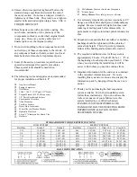
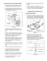
Figure 3
3.
≤
If equipped with ABS brakes, remove sensor
wires and clamps from the inboard side of the
lower arms. Save clamps for reuse.
NOTE: Remove and replace one suspension
arm at a time.
4.
≤
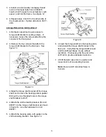
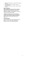
Remove the nut, cam, and cam bolt from the
axle bracket. Remove the nut and bolt from
the frame bracket. Remove the lower
suspension arm. See Figure 4
Figure 4
5.
≤
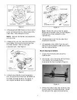
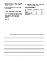
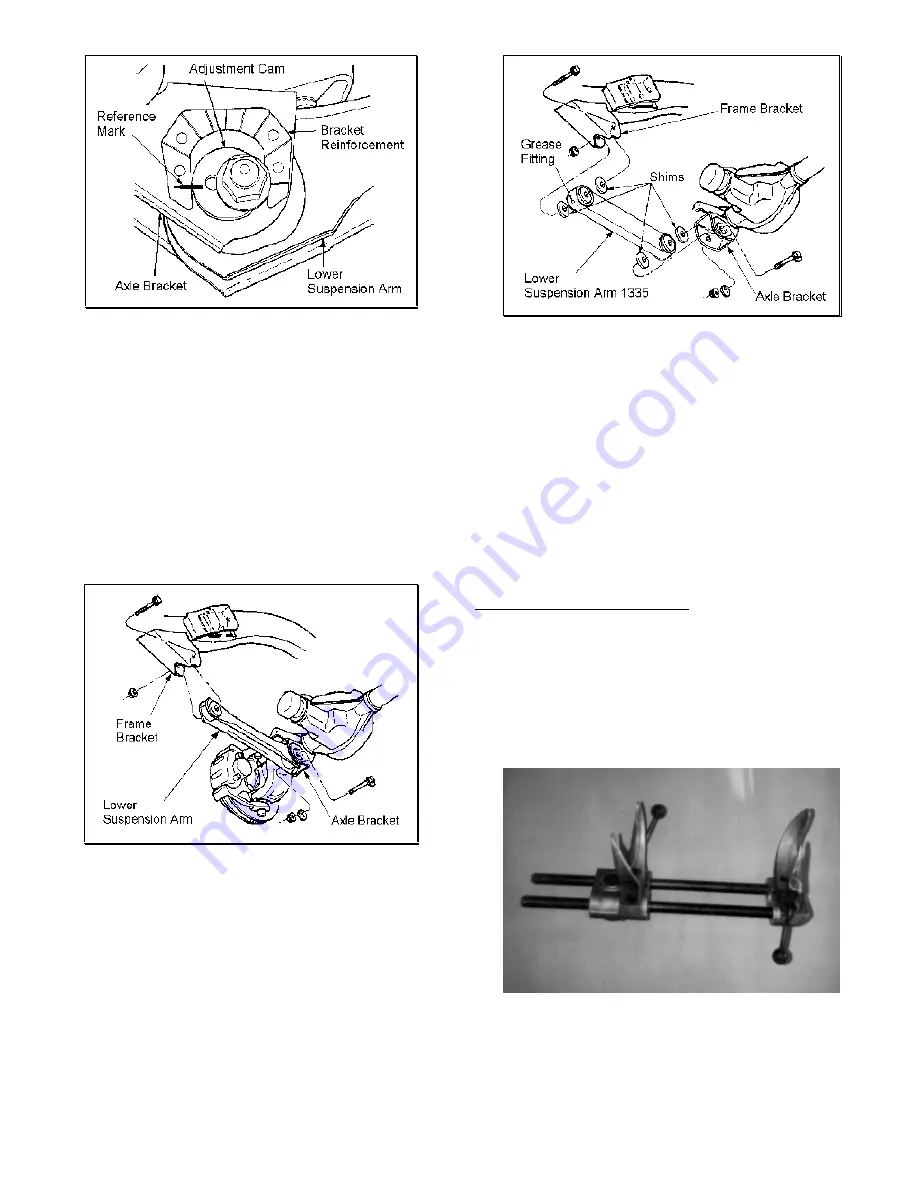
Install a new Rancho Lower Suspension
Arm, along with four shims from kit 860070, to
the frame and axle brackets. See figure 5.
Use original hardware but do not tighten.
Figure 5
Note: Position the arm so that the grease
fittings are accessible. Also, the cam adjuster
bolt may have to be installed from the
opposite way.
6.
≤
Repeat steps 4 and 5 for the other front
suspension lower arm.
7.
≤
If applicable, drill a 23/64" hole into each
lower arm and reinstall the ABS sensor wires.
Use the original clamps.
Shock & Spring Installation
1.
≤
Lower the front axle and remove the
hydraulic jack.
2.
≤
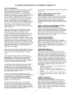
Compress a new coil spring (615 or 618) to
16" in length. Use a quality spring
compressor like the one shown in figure 6.
Figure 6
3.
≤
Place the rubber bump stop and bump stop
mount inside the compressed spring. Install
the spring into the upper and lower spring


