10
3.
≤
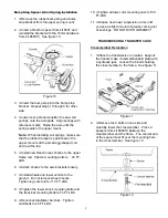
Install a conical washer and apply thread
lock to 3 flat head bolts from kit 860073.
Insert a bolt through the crossmember, each
spacer, and into the frame. See figure 12.
4.
≤
Repeat steps 2 and 3 for the other side of
the crossmember. Tighten all bolts to 45 FT-
LBS.
Linkage Relocation & Adjustment
1.
≤
Pull back carpet/mat to gain access to
torque shaft bracket mounting screws. If
necessary, loosen the screws attaching the
console to the floor panel.
2.
≤
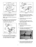
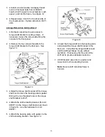
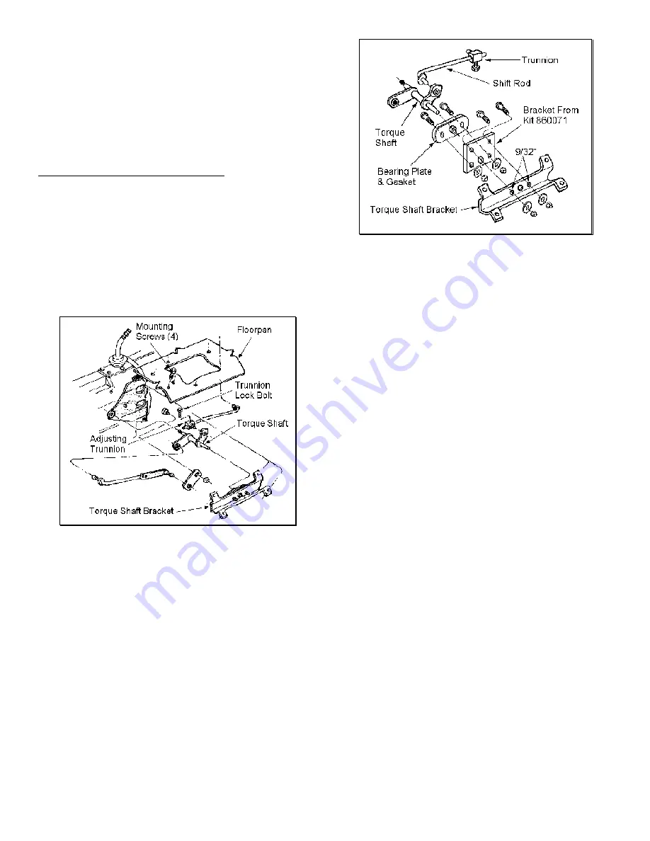
Remove the four screws that attach the
torque shaft bracket to the floor pan. See
figure 13.
Figure 13
3.
≤
Slide the torque shaft bracket off the torque
shaft, and remove the bearing plate & gasket.
Drill out the two threaded holes in the torque
shaft bracket to 9/32".
4.
≤
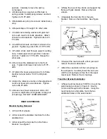
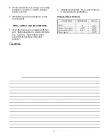
Attach the shift relocating bracket (from kit
860071) to the torque shaft bracket as shown
in figure 14. Use the hardware from kit
860071.
5.
≤
Attach the bearing plate, with gasket, to the
shift relocating bracket. See figure 14.
Figure 14
6.
≤
Insert the torque shaft into the bearing plate
and reinstall the torque shaft bracket to the
floor pan. Verify that the torque shaft is level
and the shifting linkage moves without
restriction. If necessary, file the end of the
shift rod to provide adequate clearance.
7.
≤
Shift transfer case into 4L position and
loosen lock bolt on adjusting trunnion.
Note: Be sure shift rod slides freely in
trunnion.


