background image


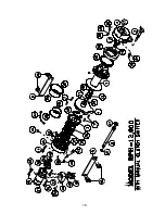
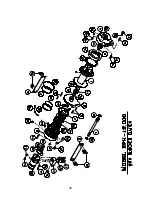
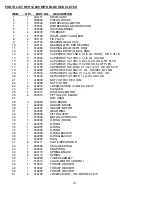
PARTS LIST RPH 12,000 WITH MANUAL CLUTCH SHIFTER 


ITEM         QTY.     PART NO.      DESCRIPTION  
 1       

1      234171     DRUM ASS'Y.  

 2       

1      276052     SHIFTER ASS'Y.-MANUAL 

 3 

306042  

PISTON-BRAKE 

 4        

1      338300     END BEARING-MOTOR 

 5        

1      338301     END BEARING-GEAR HOUSING 

 6 

338302  

HOUSING-BRAKE 

 7 

346045  

PIN-BRAKE 

 8        

1      357504   

SHAFT-INPUT/SUN GEAR 

 9        

2      395172     TIE PLATE 

10        

1      402120     BEARING-GEAR HSG. 

11        

1      402121     BEARING-MTR. END BEARING 

12       

1      412084     BUSHING-DRUM (MTR. END) 

13       

1      412085     BUSHING-DRUM (G.HSG. END) 

14        

6      414303     CAPSCREW-3/8-16NC X 2-1/2 LG. HX.HD., GR. 5 PLTD. 

15 2 

414948 


CAPSCREW 

1/2-13NC 

X 1-1/4 LG. SOC.HD.    


16 

414581  

CAPSCREW 1/2-13NC X 3/4 LG. HX.HD. GR.5 PLTD. 

17 

2  

414854  

CAPSCREW 1/4-20NC X 1/2 LG. RD.HD. SLOT PLTD. 

18     

4      414159  

CAPSCREW 5/16-18NC X 1-1/2 LG. HX HD. GR5 Z/P 

19       

1      414926     SETSCREW-3/8-16NC X 1 LG., SOCKET, NYLON 

20      

1    416016     SETSCREW-1/4-20NC X 1/4 LG., HX. SOC. HD. 

21 

418036  

NUT 3/8-16NC HEX. JAM 

22        

2      418218     LOCKWASHER-1/2 ID MED. SECT. 

23 1 

431015 


COUPLING-MOTOR 

24 2 

432018 


FITTING-7/16 

ELBOW 

25  


NOT 

USED 

26 4 

438022 


DISC-BRAKE 

27 1 

442220 


GASKET-BRAKE 


28 1 

442223 


GASKET-MOTOR 

29        

1      444085     GEAR-RING 

30 1 

456038 


FITTING-VENT 

31     

1  

458090  

MOTOR-HYDRAULIC  

32        

1      462046     O-RING (DRUM) 

33 1 

462056 


O-RING 

34 1 

462057 


O-RING 

35 1 

462058 


O-RING 

36 1 

462059 


O-RING 

BACKUP 

37 1 

462060 


O-RING 

BACKUP 

38 1 

472052 


PLUG 

39       

5      474111     PLATE-SEPARATOR 

40      

1      486080     SEAL-GEAR HSG. 

41 1 

490037 


SNAP 

RING 

42 6 

494110 


SPRING-BRAKE 

43 4 

494112 


SPRING 

44 1 

509009 


TUBE 

ASSEMBLY 

45        

1      516013     VALVE-MOTOR CONTROL 

46 1 

518037 


THRUST 

WASHER 


47 1 

518047 


THRUST 

WASHER 


48 1 

518052 


THRUST 

WASHER 

49 

418163  

LOCKWASHER – 5/16 MED SECT Z/P 

17


Summary of Contents for RPH 12,000

Page 1: ...OPERATING SERVICE AND MAINTENANCE MANUAL MODEL RPH 12 000 PLANETARY WINCH CAUTION READ AND UNDERSTAND THIS MANUAL BEFORE INSTALLATION AND OPERATION OF WINCH SEE WARNINGS ...

Page 2: ...S 5 MANUAL CLUTCH SHIFTER 5 MAINTENANCE 5 TROUBLE SHOOTING GUIDE 6 INSTRUCTIONS FOR OVERHAUL 7 12 DIMENSIONAL DRAWINGS RPH 12 000 WITH MANUAL CLUTCH SHIFTER 13 RPH 12 000 WITH AIR CYLINDER CLUTCH SHIFTER 14 PARTS LIST AND PARTS DRAWINGS RPH 12 000 WITH MANUAL CLUTCH SHIFTER 16 17 RPH 12 000 WITH AIR CYLINDER CLUTCH SHIFTER 18 19 RPH 12 000 WITH BLOCKED CLUTCH 20 21 LIMITED WARRANTY 22 ...

Page 3: ...limited warranty SPECIFICATIONS NOTE The rated line pulls shown are for the winch only Consult the wire rope manufacturer for wire rope ratings WARNINGS CLUTCH MUST BE FULLY ENGAGED BEFORE STARTING THE WINCH DO NOT DISENGAGE CLUTCH UNDER LOAD DO NOT LEAVE CLUTCH ENGAGED WHEN WINCH IS NOT IN USE STAY OUT FROM UNDER AND AWAY FROM RAISED LOADS STAND CLEAR OF CABLE WHILE PULLING DO NOT TRY TO GUIDE CA...

Page 4: ...and will meet the criteria of serving as a solid and true mounting surface When mounting the winch with other than the recommended Ramsey Angle Kit the mounting hole patterns described on page 14 must be used The mounting surface must be flat within 015 inch and sufficiently stiff to resist flexing If a steel plate is used for foot mounting it should be 750 inch thick For this mounting application...

Page 5: ...efully run winch in the reel in direction Keeping tension on end of cable spool all the cable onto the cable drum taking care to form neatly wrapped layers After installing cable check freespool operation Disengage clutch and pull on cable at a walking speed If cable birdnests loosen jam nut item 21 and turn nylon screw item 19 clockwise to increase drag on drum If cable pull is excessive loosen n...

Page 6: ...pressure PSI 2 first layer line speed FPM vs flow GPM and 3 relief valve setting PSI vs flow GPM A motor spool directional control valve is required CAUTION DO NOT EXCEED 20 G P M IF EXCEEDED MOTOR AND WINCH MAY BE DAMAGED TYPICAL LAYOUT PERFORMANCE CHARTS PERFORMANCE WITH 24 0 CU IN HYDRAULIC MOTOR SYSTEM REQUIREMENTS 2500 PSI RELIEF VALVE SETTING 15 GPM FLOW RATE 10 MICRON NOMINAL FILTRATION ...

Page 7: ...SENGAGED position cable may now be free spooled from drum TO ENGAGE CLUTCH Pull handle out rotate 90o and release handle Run the winch in reverse until the clutch handle snaps fully into the ENGAGED position DO NOT attempt to pull a load unless the handle is fully at the ENGAGED position AIR CYLINDER CLUTCH SHIFTER Refer to page 14 TO DISENGAGE CLUTCH Run the winch in the reverse reel out directio...

Page 8: ...DJUSTMENT Refer to page 10 BRAKE WILL NOT RELEASE Brake damaged Inspect and replace Refer to page 8 11 for overhaul CABLE BIRDNESTS WHEN Drag screw improperly Adjust nylon drag screw CLUTCH IS DISENGAGED adjusted Refer to pg 3 EXCESSIVE NOISE Hydraulic system flow too high Check flow rate Refer to HYDRAULIC SYSTEMS flow chart pg 4 DRUM CHATTERS Low hydraulic system flow Check flow rate Refer to HY...

Page 9: ... from brake housing item 6 by unscrewing capscrews item 15 Tap motor lightly to disengage Replace all gaskets o rings and seals with new ones during re assembly Remove coupling item 23 from brake housing Examine coupling for signs of wear replace if necessary If necessary remove valve item 45 from motor by removing capscrews item 19 and lockwashers item 49 If valve is removed make sure two square ...

Page 10: ...m brake housing Examine brake discs item 26 for signs of wear and replace if necessary Examine o rings items 34 35 and backup rings items 36 37 for signs of wear Remove o rings and backup rings from grooves in brake piston item 3 Remove and examine springs items 42 43 for damage replace if necessary Examine fitting item 30 to assure that fittings are in proper working condition replace if necessar...

Page 11: ...well oiled o ring item 33 into groove inside of end bearing and press new bearing item 11 into end bearing Press bushing item 12 onto end bearing and dip o ring item 32 in oil and seat into groove of end bearing Remove seal item 40 from gear housing end bearing item 5 Loosen nut item 21 and remove nylon setscrew item 18 and remove ring gear item 29 from gear housing end bearing if necessary Remove...

Page 12: ...as shown Thread assembly with handle engaged in cylinder slot into the end bearing Pull drum toward the brake housing end bearing to remove play Hold drum in the position and continue threading the shifter assembly in until the gap between the end of the handle and cylinder is 7 16 0 1 16 inch and handle is in the horizontal position as shown below NOTE This gap will vary with drum endplay With th...

Page 13: ...em 26 and separator plates item 39 must be clean and free of grease and oil Place piston over pins item 7 and on top of springs item 42 Place separator plates item 39 and brake disc alternately on top of piston as shown below Press larger diameter end of 4 springs item 43 into pockets in brake housing item 6 Place gasket item 27 on top of end bearing item 4 Place brake housing over brake parts wit...

Page 14: ...sing item 6 Use 2 capscrews item 15 with lockwashers item 22 and torque to 87 ft lbs 118 Nm each Securely connect tube item 44 to elbows item 24 in valve item 45 and in bottom of brake housing item 6 Apply at least 550 PSI hydraulic system pressure to release brake and verify that brake releases by observing that the winch drum rotates ...

Page 15: ...MODEL RPH 12000 WITH MANUAL CLUTCH SHIFTER 13 ...

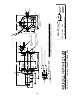
Page 16: ...END 1 75 875 14 SAE STRAIGHT THREAD O RING PORT TYP 2 PLACES 88 22 4 44 5 4 88 124 0 A 5 53 12 25 311 2 9 75 247 7 100 0 3 94 BARREL DIA DRUM SIDE OF WINCH PRESSURE LINE TO DISENGAGE CONNECT 80 TO 150 PSI CLUTCH 125 27NPT PORT 231 6 SCHEMATIC ELECTRICAL IS ENGAGED ON WHEN CLUTCH INDICATOR LIGHT 12V BATTERY _ SWITCH CONNECTOR BUTT TYP TYP 2 25 57 2 TAPPED HOLE TYP 4 PLACES EACH 500 13UNC X 75 19 1 ...

Page 17: ...15 NOTES ...

Page 18: ...16 ...

Page 19: ...CAPSCREW 5 16 18NC X 1 1 2 LG HX HD GR5 Z P 19 1 414926 SETSCREW 3 8 16NC X 1 LG SOCKET NYLON 20 1 416016 SETSCREW 1 4 20NC X 1 4 LG HX SOC HD 21 1 418036 NUT 3 8 16NC HEX JAM 22 2 418218 LOCKWASHER 1 2 ID MED SECT 23 1 431015 COUPLING MOTOR 24 2 432018 FITTING 7 16 ELBOW 25 NOT USED 26 4 438022 DISC BRAKE 27 1 442220 GASKET BRAKE 28 1 442223 GASKET MOTOR 29 1 444085 GEAR RING 30 1 456038 FITTING ...

Page 20: ...18 ...

Page 21: ... 4 414159 CAPSCREW 5 16 18NC X 1 1 2 LG HX HD GR 5 Z P 21 1 414926 SETSCREW 3 8 16NC X 1 LG SOCKET NYLON 22 1 416016 SETSCREW 1 4 20NC X 1 4 LG HX SOC HD 23 1 418036 NUT 3 8 16NC HEX JAM 24 2 418218 LOCKWASHER 1 2 ID MED SECT 25 1 431015 COUPLING MOTOR 26 2 432018 FITTING 7 16 ELBOW 27 NOT USED 28 4 438022 DISC BRAKE 29 1 442220 GASKET BRAKE 30 1 442223 GASKET MOTOR 31 1 444085 GEAR RING 32 1 4560...

Page 22: ...20 ...
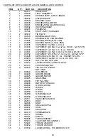
Page 23: ...8 16NC X 1 LG SOCKET NYLON 19 1 416016 SETSCREW 1 4 20NC X 1 4 LG HX SOC HD 20 1 416030 SETSCREW 5 8 18NF X 1 LG HX SOC HD 21 1 418036 NUT 3 8 16NC HEX JAM 22 1 418088 NUT 5 8 18NF 23 2 418218 LOCKWASHER 1 2 ID MED SECT 24 1 426048 PLUNGER 25 1 431015 COUPLING MOTOR 26 2 432018 FITTING 7 16 ELBOW 27 NOT USED 28 4 438022 DISC BRAKE 29 1 442220 GASKET BRAKE 30 1 442223 GASKET MOTOR 31 1 444085 GEAR ...

Page 24: ...upon which repair or alterations have been made unless authorized by Manufacturer or for equipment misused neglected or which has not been installed correctly RAMSEY WINCH shall in no event be liable for special or consequential damages RAMSEY WINCH makes no warranty in respect to accessories such as being subject to the warranties of their respective manufacturers RAMSEY WINCH whose policy is one...

Reviews: