background image

COPYRIGHT © 2019 SANDVIK MINING AND CONSTRUCTION OY

Page 16 - Operation

Safety

RPV14R, RPV22R, RPV29R, RPV39R, RPV53R, RPV75R 

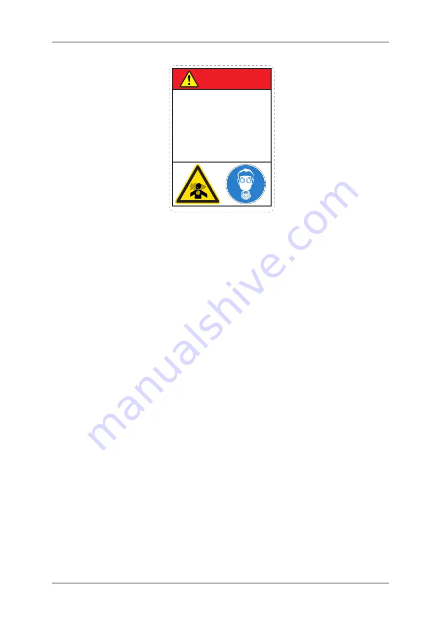
Airborne pollutants are microscopic particles, which will damage your health when
inhaled. Aiborne pollutants on construction sites can be for example silica dust, oil
fumes or diesel exhaust particles, visible or invisible. Especially in demolition sites,
there may be other dangerous substances, such as asbestos, lead paints or other
chemical substances. 

The effect of airborne pollutants may be immediate if the substance is poisonous.
The main danger with airborne pollutants comes from long term exposure, where
particles are inhaled but not removed from the lungs. The disease is called silicosis,
asbestosis or other, and will result in death or serious injury.

To protect yourself from airborne pollutants, always keep excavator doors and
windows closed during operation. Excavators with pressurized cabins should be
utilized in product operation. Proper maintenance of fresh air filters of the excavator
is essential. Where pressurized cabins are not available, proper respirators must be
utilized.

Stop working when bystanders are in the area of airborne pollutants and make sure
they have proper respirators. Respirators are as important for bystanders as hard
hats.Respirators for both operator and bystanders must be approved by the
respirator manufacturer for the application in question. It is essential that the
respirators protect from the tiny dust particles which cause silicosis and which may
cause other serious lung diseases. Do not use the product until you are sure the
respirators are working properly. This means each respirator must be checked to
make sure that it is clean, that its filter has been changed, and to otherwise make sure
the respirator will protect in the way it is meant to.

Always make sure dust has been cleaned off your boots and clothes when you leave
your shift. The smallest particles of dust are the most harmful. They may be so fine
that you cannot see them. Remember, you MUST protect yourself and bystanders
from the danger of breathing or inhaling dust.

Always follow local laws and regulations for airborne pollutants in the working
environment.

R010

3

49

DUST HAZARD

Breathing dust will cause death
or severe injury.

Always wear approved
respirator.

DANGER

169410_ENG-1

Summary of Contents for RPV14R

Page 1: ...Original instructions 3 19 OPERATOR S MANUAL OMRPVRENG 319 ROTATING PULVERIZER RAMMER RPV14R RPV22R RPV29R RPV39R RPV53R RPV75R ...

Page 2: ...enance procedures 48 2 Turning and changing cutting blades 49 Wear limits adjustments and torques for cutting blades 49 Turning and changing cutting blades 50 3 Replacing teeth 52 Welding tools and torques for cutting blade screws 52 Changing a tooth 52 4 Replacing crushing plate 56 Tightening torque for crushing plate 56 Removal of crushing plate 56 5 Changing oil in the rotation unit 58 Diagram ...

Page 3: ...Operation Page 3 COPYRIGHT 2019 SANDVIK MINING AND CONSTRUCTION OY RPV14R RPV22R RPV29R RPV39R RPV53R RPV75R OPERATION ...

Page 4: ...ven in kilograms kg In some cases an other unit follows in parenthesis For example 28 litres 7 4 US gal The specifications and designs presented in this manual are subject to change without prior notice SYMBOLS USED IN THIS MANUAL This symbol identifies important safety messages within this manual Carefully read the message that follows Failure to understand and obey this safety warning could resu...

Page 5: ...ly you must also be a competent operator of the carrier Do not use or install it if you cannot use the carrier The product is a powerful tool Used without proper care it can cause damage Do not rush when you are learning to use the product Take your time and most importantly take it safely Do not guess If there is anything you do not understand ask your local dealer Improper operation lubrication ...

Page 6: ...py of it after the installation inspection and that it is correctly filled out INSTALLATION INSPECTION An installation inspection must be carried out after the product has been installed on the carrier During the installation inspection certain specifications operating pressure oil flow etc are checked so that they are within given limits See Product specifications on page 64 1 4 SPARE PART ORDERS...

Page 7: ...ecific product See the following figure for the location of the serial number on your product model CONTENT OF THE PRODUCTIDENTIFICATION PLATE 1 Demolition tool 2 Serial number 3 Model 4 Weight kg 5 Min working weight kg 6 Manufactured 7 Max cylinder pressure bar 8 Max rotation pressure bar 9 Max cylinder oil flow l min 10 Max rotation oil flow l min 11 Manufactured by Sandvik Mining and Construct...

Page 8: ...g components which weigh 23 kg 51 lb or more to avoid back injury Make sure all chains hooks slings etc are in good condition and are in the correct capacity Make sure hooks are positioned correctly Do not side load the lifting eye during a lifting operation PROVIDED LIFTING POINTS The lifting points located on the product frame are to be used solely to lift or handle the product itself The liftin...

Page 9: ...al tools for tightening make sure not to overstrain the shank Before lifting make sure that the rope and or hook is stretched When two lifting points are used the lifting capacity depends on the angle of the lifting chains The angle should not be less than 45 as shown in the illustration When the lifting eye screws are tightened both rings should be aligned The loading capacity calculation applies...

Page 10: ...lways ensure the procedure you choose is safe for you and others Do not lift the load over people No one must be under the hoisted load Do not lift people and never ride the hoisted load Keep people clear from the lift area Avoid side pull of the load Make sure you take up the slack slowly Start and stop carefully Lift the load a few centimeters and verify it before proceeding Make sure the load i...

Page 11: ...roduct introduction RPV14R RPV22R RPV29R RPV39R RPV53R RPV75R 3 4 MAIN PARTS The main parts of the rotating pulverizer are shown below A Mounting bracket B Jaw C Frame D Crushing plate E Crushing tooth F Cutting blades G Cylinder H Thrust bearing MB010018 A H C E D F B G ...

Page 12: ... protection in their everyday work When working with a Rammer product please follow these guidelines Dispose of packaging materials properly Wood and plastic can be burned or recycled Deliver the steel belts to metal recycling center Protect the environment from oil spills In case of hydraulic oil leaks the product should be serviced immediately Follow the product s greasing instructions and avoid...

Page 13: ...r made unsafe by the method of operation or maintenance procedures you choose Safety is not just a matter of responding to the warnings All the time you are working with your product you must pay attention to what hazards there might be and how to avoid them Do not work with the product until you are sure that you can control it Do not start any job until you are sure that you and those around you...

Page 14: ...met safety shoes safety glasses well fitting overalls ear protectors and industrial gloves Keep cuffs fastened Do not wear a necktie or scarf Keep long hair restrained PRACTICE You and others can be killed or injured if you perform unfamiliar operations without practicing them first Practice away from the job site in a clear area Keep other people away Do not perform new operations until you are s...

Page 15: ...lectric cables gas and water pipes etc Mark the positions of cables and pipes Poor visibility can cause accidents and damage Make sure that visibility and lighting in the working area are adequate Worksites can be noisy Wear ear protection to prevent personal injury BANKS AND TRENCHES Banked material and trenches can collapse Do not work too close to banks and trenches where there is a danger of c...

Page 16: ...re not available proper respirators must be utilized Stop working when bystanders are in the area of airborne pollutants and make sure they have proper respirators Respirators are as important for bystanders as hard hats Respirators for both operator and bystanders must be approved by the respirator manufacturer for the application in question It is essential that the respirators protect from the ...

Page 17: ...dard EN 474 1 on safety of earth moving machinery requires that adequate operator s protection such as bullet proof glass mesh guard or an equivalent protection is used Keep the cabin windows and doors closed during operation Window bars are recommended to protect the windows from flying debris CRUSHING HAZARD The safety label on the product is shown below CRUSHING HAZARD Contact with moving parts...

Page 18: ...rformance by unapproved modifications HYDRAULIC FLUID Fine jets of hydraulic fluid at high pressure can penetrate the skin Do not use your fingers to check for hydraulic fluid leaks Do not put your face close to suspected leaks Hold a piece of cardboard close to suspected leaks and then inspect the cardboard for signs of hydraulic fluid If hydraulic fluid penetrates your skin seek medical help imm...

Page 19: ...rom the carrier Be aware of possible unexpected jaw movements while maintaining product LIFTING EQUIPMENT You can be injured if you use faulty lifting equipment Make sure that lifting equipment is in good condition Make sure that the lifting tackle complies with all local regulations and is suitable for the job Make sure that the lifting equipment is strong enough for the job and you know how to u...

Page 20: ...messages the messages in the product safety labels and the instructions set forth in the manuals to avoid death or severe injury Keep the safety labels clean and visible at all times Check the condition of safety labels daily Safety labels and instructions which have disappeared been damaged painted over come loose or do not meet the legibility requirements for safe viewing distance must be replac...

Page 21: ... number Model Manufactured Weight kg Min working weight kg Max cylinder pressure bar Max rotation pressure bar Max cylinder oil flow l min Max rotation oil flow l min FLYING OBJECTS HAZARD Fragments fly up to 40 m 130 ft and could cause death or severe injury Stop operation when a person enters hazard zone Wear approved personal protective equipment 169410_ENG 2 IGNORING INSTRUCTIONS HAZARD Faulty...

Page 22: ... Serial number Model Manufactured Weight kg Min working weight kg Max cylinder pressure bar Max rotation pressure bar Max cylinder oil flow l min Max rotation oil flow l min FLYING OBJECTS HAZARD Fragments fly up to 40 m 130 ft and could cause death or severe injury Stop operation when a person enters hazard zone Wear approved personal protective equipment 169410_ENG 2 DUST HAZARD Breathing dust w...

Page 23: ...ble hoses and fittings For product installation secondary relief valves in the bucket cylinder circuit and the carrier auxiliary circuit are needed If the carrier does not have a suitable kit to run attachments one must be built This may require a more complex installation including new piping and additional valves such as a flow control valve or pressure relief valve Suitable kits can be ordered ...

Page 24: ...ETH AND CUTTING BLADES Jaws The jaws are operated by the hydraulic cylinder One jaw is fixed and the other equipped with breaking teeth is moving Crushing is performed using the crushing teeth of the jaws Crushing teeth Crushing is performed using the crushing teeth of the jaws The long lasting convex teeth are made of special steel They are fastened with screws and can be replaced Crushing plate ...

Page 25: ... carrier with people around it The product as a standard assembly must not be used under water It must be adapted for underwater applications Contact your local dealer for more information on underwater use After operating the product under water or in environments close to the sea carefully wash the product Subsequently disassemble the hinges and carefully clean the pins and bushings to remove al...

Page 26: ...ng operation Remove the cotter pin and take out the locking pin Prepare the carrier for normal excavation work Move the carrier to the required position Set the drive to neutral Set the engine speed to the recommended engine RPM NOTICE Carefully operate the carrier controls to place the product and boom into the working position Quick and careless boom movements can result in damage to the product...

Page 27: ...se the jaws to crush The best crushing result is obtained by using the whole tooth area of the jaws NOTICE Avoid using cutting blades for crushing Doing so may damage the blades When crushing very large concrete blocks start crushing from the outer edges of the concrete Use a safety screen to protect the operator from flying debris Keep the cabin windows and doors closed during operation MB010054 ...

Page 28: ...of the fixed jaw side and close the jaws to cut For the best possible cutting performance and to avoid damaging the product only use cutting blades for cutting The product is intended for pulverizing Do not use the product as a lever or to strike hit or ram objects Do not use the side of the product to move concrete or objects Do not use the product for lifting Lifting eyes on product are for stor...

Page 29: ...the product to move the excavator When operating the product make sure that it does not make contact with the carrier boom or hydraulic lines Do not operate the jaws with the carrier s boom stick or bucket cylinders at the end of their stroke either fully extended or retracted This may damages the carrier MB010060 MB010061 MB010062 ...

Page 30: ...inder rod or shield plate may cause rod seal breakage and oil leaks Always remove demolition debris from the product Getting steel frame or rebar between the jaws and cylinder rod clevis can damage the cylinder rod or jaws Getting steel bars in the clearance between the cylinder and the base of the fixed jaw can damage the main shaft To avoid a dangerous fall ensure that the structure your carrier...

Page 31: ...g area damp with water jets Stay more than 10 meters 33 feet away from live overhead electric cables with any part of the machine The bearings must be well greased during operation Make regular inspections during operation If no grease is visible the bearings require more frequent greasing If bearings are covered with excessive grease they require less frequent greasing MB010067 20 m MB010077 ...

Page 32: ...e the product must always be released before opening hose connections Warning Hot hydraulic fluid can cause severe injuries Warning The thrust bearing must be locked to prevent the product from rotating during maintenance or transportation 1 Position the product horizontally on the floor 2 Stop the carrier engine Operate the boom and product controls to release pressure trapped inside hoses 3 Clos...

Page 33: ... 5 Remove the mounting bracket pins and other parts 6 Install the locking pins and cotter pins 7 Move the carrier aside if needed INSTALLATION ON THE CARRIER Warning The residual air in the hoses must always be removed before operation 1 Remove the cotter pins and take out the locking pins 2 Install the product in the same manner as mounting a bucket Install bucket pins MB010082 MB010088 MB010090 ...

Page 34: ...osing and the lower pressure line to the connection fitting jaw opening in order to have the maximum clamping force Remove the cap from the fitting of the hydraulic hoses connecting the excavator and the crusher Make sure that the hose fittings are perfectly clean and dust free and attach them to the machine by tightening the screws or the fittings Note The hydraulic rotation motor can operate wit...

Page 35: ... too close to the carrier 5 5 SPECIAL CONDITIONS OF USE The product may require modifications special operating techniques increased maintenance or special wear items if it is used in conditions that differ from normal breaking or demolition work Special conditions of use are Underwater operations Operations in extremely low or high temperatures Use of special hydraulic fluids Operations with spec...

Page 36: ...of the product are protected from rust and the product is ready to be used whenever necessary 1 Make sure your storage area is dry 2 To avoid damaging the cylinder rod operate the cylinder to the shortest position by leaving the jaws open 3 Insert blocks under the product to keep it off the ground If the product is stored outside cover it to prevent rusting 4 Apply grease to all product parts Prot...

Page 37: ...Lubrication Page 37 COPYRIGHT 2019 SANDVIK MINING AND CONSTRUCTION OY RPV14R RPV22R RPV29R RPV39R RPV53R RPV75R LUBRICATION ...

Page 38: ...cessive greasing Dispose of empty grease containers appropriately The greasing points of the product are marked with the following sticker Item Recommended greases Greasing interval Pins and bushings every 8 hours Thrust bearing every 40 80 hours Additives molybdenum disulfide Minimum working temperature below lowest ambient temperature Penetration 0 2 NLGI No reaction with hydraulic oils Water re...

Page 39: ...Lubrication Page 39 COPYRIGHT 2019 SANDVIK MINING AND CONSTRUCTION OY Greasing RPV14R RPV22R RPV29R RPV39R RPV53R RPV75R The greasing points of the product are shown below MB020002 ...

Page 40: ...il must be monitored If the temperature of the hydraulic oil exceeds 80 C 176 F an auxiliary oil cooler is needed The oil viscosity must be between 1000 20 cSt while the product is being used When the product is used continuously the temperature of the hydraulic oil normalizes at a certain level depending on conditions and on the carrier The temperature in the tank must not exceed the maximum allo...

Page 41: ...ydraulic oil in continuous use is in the ideal area on the chart and the hydraulic system is used to best advantage Problems due to incorrect hydraulic oil viscosity in the product Oil too thick Difficult start up Stiff operation Danger of cavitation Sticky valves Filter bypass opens impurities in the oil are not removed Oil too thin Efficiency losses internal leaks Damage to gaskets and seals lea...

Page 42: ... oils 2 2 OIL COOLER The carrier hydraulic system must be able to maintain a temperature within an acceptable level during the product operation This is because 1 Seals wipers membranes and other parts manufactured from the corresponding materials can normally stand temperatures up to 80 C 176 F 2 The higher the temperature is the less viscous the oil gets thus losing its capability to lubricate A...

Page 43: ...roduct work the carrier oil filter must fulfill the following specifications The oil filter must allow maximum particle size of 25 microns 0 025 mm The oil filter material must be man made fibre cloth or very fine gauge metallic mesh to withstand pressure fluctuations The oil filter must have a nominal flow capacity of at least twice the product s maximum flow In general oil companies guarantee ne...

Page 44: ...on of valves Binding spools Rapid wear of parts Blocking of small holes Note Component damage is only a symptom The trouble itself will not be cured by removing the symptom After any component damage due to impurities in the oil the entire hydraulic system must be cleaned Dismantle clean and reassemble the product and change the hydraulic oil ...

Page 45: ...Maintenance Page 45 COPYRIGHT 2019 SANDVIK MINING AND CONSTRUCTION OY RPV14R RPV22R RPV29R RPV39R RPV53R RPV75R MAINTENANCE ...

Page 46: ...ulic oil before assembly Remember to grease the product parts regularly according to the instructions in this manual Prior to maintenance or inspection operate all the control levers to their fully extended stroke This will release pressure within the hydraulic piping and prevent unexpected movement of the jaw and loss of oil through the hydraulic lines Close the jaws during maintenance or inspect...

Page 47: ... body for wear 2 Check the pins and bushings for wear 3 Check the cylinder rod seals and connection points for wear Tighten if necessary 4 Observe hydraulic oil temperature for all lines and connections 5 Check that the product works smoothly by operating the jaws 6 Tighten connections if necessary EVERY 40 80 HOURS Grease the thrust bearing Adapt the greasing interval and amount of grease to work...

Page 48: ...anything in any boom stick position 1 4 MAINTENANCE INTERVALS IN SPECIAL APPLICATIONS The service interval is considerably shorter with special applications such as underwater use In special applications consult your local dealer for the correct service intervals The product as a standard assembly must not be used under water It must be adapted for underwater applications Contact your local dealer...

Page 49: ...e grade 12 9 M8 25 Nm 18 lbf ft 35 Nm 26 lbf ft 42 Nm 31 lbf ft M10 50 Nm 37 lbf ft 70 Nm 52 lbf ft 85 Nm 63 lbf ft M12 85 Nm 63 lbf ft 120 Nm 89 lbf ft 145 Nm 107 lbf ft M14 135 Nm 100 lbf ft 190 Nm 140 lbf ft 230 Nm 170 lbf ft M16 210 Nm 155 lbf ft 295 Nm 218 lbf ft 355 Nm 262 lbf ft M18 290 Nm 214 lbf ft 410 Nm 302 lbf ft 490 Nm 361 lbf ft M20 410 Nm 302 lbf ft 575 Nm 424 lbf ft 690 Nm 509 lbf ...

Page 50: ... the hydraulic piping and prevent unexpected movement of the jaw and loss of oil through the hydraulic lines Warning Support the jaw to prevent it from closing unexpectedly during maintenance Used cutting blades can be recycled Contact your dealer for more information about local regulations of recycling 1 Position the product on level ground 2 Support the jaw 3 Make sure the carrier s transmissio...

Page 51: ... 7 Grind the surfaces to flush all burrs from the cutting blade and cutter base If burrs remain on the surface the cutting blade will not have proper contact with the cutting blade base This will cause the cutting blade to break 8 With a feeler gauge check that the clearance between the two cutting blades is the required 0 2 1 2 mm 0 008 0 05 in If necessary restore the correct clearance by insert...

Page 52: ...plates Item Welding tool Repair of parent installation of tooth MIG wire DIN 8559 SG 2 Welding rod DIN 1913 E 51 53 B 10 Hardfacing MIG wire DIN 8555 SG 6 60 Welding rod DIN 8555 E 6 55 Screw Tightening torque grade 8 8 Tightening torque grade 10 9 Tightening torque grade 12 9 M8 25 Nm 18 lbf ft 35 Nm 26 lbf ft 42 Nm 31 lbf ft M10 50 Nm 37 lbf ft 70 Nm 52 lbf ft 85 Nm 63 lbf ft M12 85 Nm 63 lbf ft...

Page 53: ...ntenance teeth are lost during product operation stop operation immediately or you will damage the housings on the product body During complete shutdown make sure that the jaw rest on the central tooth of the product framework If you do not it will be necessary to replace the interchangeable part where the central tooth is located WARNING When replacing the interchangeable plate close the mobile j...

Page 54: ... product on the ground at a 30 incline so that the side with the tooth to be replaced faces upward Remove the fastening pin 2 together with the hardened resin 5 with of the supplied pin extractor striking the end with a hammer see illustration 2 Extract the tooth 1 from its housing Carefully clean the space 6 which contained the resin and eliminate any residue 3 Place the product on the ground at ...

Page 55: ...ge containing resin and two mixing tubes 7 Remove the plug by unscrewing the screw and insert the mixing tube by fastening it with the nut Place everything on the pistol NOTICE To prevent the product leaking hold the pistol vertically 8 Press the pistol handgrip and keeping the pistol vertical push the resin into the mixing tube 9 Press three times to release all of the resin Insert the STIMIX res...

Page 56: ...e the screws and washers Screw Tightening torque grade 8 8 Tightening torque grade 10 9 Tightening torque grade 12 9 M8 25 Nm 18 lbf ft 35 Nm 26 lbf ft 42 Nm 31 lbf ft M10 50 Nm 37 lbf ft 70 Nm 52 lbf ft 85 Nm 63 lbf ft M12 85 Nm 63 lbf ft 120 Nm 89 lbf ft 145 Nm 107 lbf ft M14 135 Nm 100 lbf ft 190 Nm 140 lbf ft 230 Nm 170 lbf ft M16 210 Nm 155 lbf ft 295 Nm 218 lbf ft 355 Nm 262 lbf ft M18 290 N...

Page 57: ...G AND CONSTRUCTION OY Replacing crushing plate RPV14R RPV22R RPV29R RPV39R RPV53R RPV75R 4 Remove the old crushing plate 5 Fix the new crushing plate properly into place 6 Install the screws and washers Tighten parts to the specified torques MB030016 ...

Page 58: ...TION UNIT Warning Support the jaw to prevent it from closing unexpectedly during maintenance The oil must be changed after the first 150 working hours Afterwards it must be changed every 2000 operating hours or at least once a year Change the oil while the rotation unit is hot Wash the internal parts with the proper liquids before introducing the new oil Item Drain plug A Filler cap B Level plug C...

Page 59: ...he lubricant must not exceed 80 C 176 F Whenever this value is in danger of being exceeded forcibly cool the oil NOTICE Change the oil while the rotation unit is hot 1 Position the product on level ground The rotation unit and product must be in an upright position 2 Support the jaws 3 Unscrew the filler cap B and the drain plug A 4 Completely empty oil in the rotation unit 5 Replace the drain plu...

Page 60: ...des and adjust If necessary change the cutting blades See Turning and changing cutting blades on page 49 CUTTING BLADE DOES NOT FIT PROPERLY ONTO THE CUTTER BASE Refit and tighten with bolts See Turning and changing cutting blades on page 49 INCORRECT CLEARANCE BETWEEN THE BLADES AND BASE Check the clearance and adjust See Turning and changing cutting blades on page 49 DROP IN HYDRAULIC PRESSURE O...

Page 61: ...e hose end and tighten OIL LEAKAGE AT SWIVEL JOINT The product must be serviced in an authorized Rammer service shop CYLINDER SEALS ARE DAMAGED The product must be serviced in an authorized Rammer service shop 6 6 PRODUCT DOES NOT ROTATE ROTATION IS LOCKED Open the rotation lock See Mounting and dismounting the product on page 32 6 7 FURTHER ASSISTANCE FURTHER ASSISTANCE If further assistance is r...

Page 62: ...COPYRIGHT 2019 SANDVIK MINING AND CONSTRUCTION OY Page 62 Maintenance Troubleshooting RPV14R RPV22R RPV29R RPV39R RPV53R RPV75R ...

Page 63: ...Specifications Page 63 COPYRIGHT 2019 SANDVIK MINING AND CONSTRUCTION OY RPV14R RPV22R RPV29R RPV39R RPV53R RPV75R SPECIFICATIONS ...

Page 64: ... 300 350 bar 4350 5075 psi Oil flow 100 180 l min 26 4 47 6 gal min Hose connections 3 4 GAS Operating pressure rotation 190 200 bar 2755 2900 psi Oil flow rotation 10 15 l min 2 6 4 0 gal min Connections rotation 1 2 GAS Max diameter to be cut 35 mm 1 38 in Jaw closing time at max oil flow 2 2 s Jaw opening time at max oil flow 1 1 s No of cycles per minute at max oil flow 16 3 cycles min Optimum...

Page 65: ...5 COPYRIGHT 2019 SANDVIK MINING AND CONSTRUCTION OY Product specifications RPV14R RPV22R RPV29R RPV39R RPV53R RPV75R 1 2 MAIN DIMENSIONS RPV14R MB040020 580 1710 410 Ø21 16 pcs 498 550 110 110 110 110 29 125 29 130 130 125 ...

Page 66: ...0 5075 psi Oil flow 180 200 l min 47 6 52 8 gal min Hose connections SAE 6000 psi 1 Operating pressure rotation 130 150 bar 1885 2175 psi Oil flow rotation 30 40 l min 7 9 10 6 gal min Connections rotation 1 2 GAS Max diameter to be cut 55 mm 2 17 in Jaw closing time at max oil flow 1 4 s Jaw opening time at max oil flow 2 3 s No of cycles per minute at max oil flow 16 3 cycles min Optimum oil tem...

Page 67: ...PYRIGHT 2019 SANDVIK MINING AND CONSTRUCTION OY Product specifications RPV14R RPV22R RPV29R RPV39R RPV53R RPV75R 1 4 MAIN DIMENSIONS RPV22R MB040021 750 2130 475 Ø25 16 pcs 620 620 137 137 137 137 36 142 5 25 142 5 142 5 142 5 ...

Page 68: ...0 5075 psi Oil flow 200 220 l min 52 8 58 1 gal min Hose connections SAE 6000 psi 1 Operating pressure rotation 100 115 bar 1450 1670 psi Oil flow rotation 30 40 l min 7 9 10 6 gal min Connections rotation 1 2 GAS Max diameter to be cut 61 mm 2 40 in Jaw closing time at max oil flow 2 3 s Jaw opening time at max oil flow 2 3 s No of cycles per minute at max oil flow 13 2 cycles min Optimum oil tem...

Page 69: ...9 COPYRIGHT 2019 SANDVIK MINING AND CONSTRUCTION OY Product specifications RPV14R RPV22R RPV29R RPV39R RPV53R RPV75R 1 6 MAIN DIMENSIONS RPV29R MB040022 900 2400 550 Ø29 16 pcs 700 700 160 160 160 160 30 160 30 160 160 160 ...

Page 70: ...5075 psi Oil flow 220 280 l min 58 1 74 0 gal min Hose connections SAE 6000 psi 1 1 4 Operating pressure rotation 100 115 bar 1450 1670 psi Oil flow rotation 30 40 l min 7 9 10 6 gal min Connections rotation 1 2 GAS Max diameter to be cut 66 mm 2 60 in Jaw closing time at max oil flow 2 9 s Jaw opening time at max oil flow 2 7 s No of cycles per minute at max oil flow 10 6 cycles min Optimum oil t...

Page 71: ...COPYRIGHT 2019 SANDVIK MINING AND CONSTRUCTION OY Product specifications RPV14R RPV22R RPV29R RPV39R RPV53R RPV75R 1 8 MAIN DIMENSIONS RPV39R MB040023 1000 2680 620 Ø32 18 pcs 800 740 148 30 148 148 148 148 170 30 170 170 170 ...

Page 72: ...75 psi Oil flow 280 320 l min 74 0 84 5 gal min Hose connections SAE 6000 psi 1 1 4 Operating pressure rotation 100 115 bar 1450 1670 psi Oil flow rotation 30 40 l min 7 9 10 6 gal min Connections rotation 1 2 GAS Max diameter to be cut 68 mm 2 68 in Jaw closing time at max oil flow 3 0 s Jaw opening time at max oil flow 2 8 s No of cycles per minute at max oil flow 10 2 cycles min Optimum oil tem...

Page 73: ...OPYRIGHT 2019 SANDVIK MINING AND CONSTRUCTION OY Product specifications RPV14R RPV22R RPV29R RPV39R RPV53R RPV75R 1 10 MAIN DIMENSIONS RPV53R MB040043 1100 3000 660 Ø32 18 pcs 800 740 148 30 148 148 148 148 170 30 170 170 170 ...

Page 74: ... psi Oil flow 500 600 l min 132 1 158 5 gal min Hose connections SAE 6000 psi 1 1 2 Operating pressure rotation 140 150 bar 2030 2175 psi Oil flow rotation 50 60 l min 13 2 15 9 gal min Connections rotation 1 2 GAS Max diameter to be cut 70 mm 2 76 in Jaw closing time at max oil flow 2 2 s Jaw opening time at max oil flow 3 8 s No of cycles per minute at max oil flow 10 0x cycles min Optimum oil t...

Page 75: ...RIGHT 2019 SANDVIK MINING AND CONSTRUCTION OY Product specifications RPV14R RPV22R RPV29R RPV39R RPV53R RPV75R 1 12 MAIN DIMENSIONS RPV75R MB040044 1250 3600 750 Ø39 20 pcs 1140 1020 165 165 70 170 170 165 165 225 60 225 225 225 ...

Page 76: ...RPV29R Model RPV39R Model RPV53R Model RPV75R Place of issue Mirandola Italy Date of issue dd mm yyyy to which this declaration relates conforms to the Basic Safety and Health Requirements of Directive 2006 42 EC Harmonized standards applied EN474 1 EN474 5 EN12100 1 EN12100 2 Other standards applied ISO 10567 92 ISO 7451 83 SAE J1097 DIN 15019 DIN 24086 Name and position of issuer N N Signature o...

Page 77: ...Page 77 COPYRIGHT 2019 SANDVIK MINING AND CONSTRUCTION OY ...

Page 78: ...COPYRIGHT 2019 SANDVIK MINING AND CONSTRUCTION OY Page 78 ...

Page 79: ...Page 79 COPYRIGHT 2019 SANDVIK MINING AND CONSTRUCTION OY ...

Page 80: ...dvik Mining and Construction Oy Breakers Lahti Taivalkatu 8 P O Box 165 FI 15101 Lahti Finland Phone Int 358 205 44 151 Telefax Int 358 205 44 150 www rammer com 75 12 14133 42 20 343 75 12 14133 45 28 161 ...

Reviews: