background image

www.raisecom.com                                                                                                                                     

 User Manual


13           

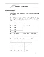
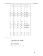
Bit 1 

Bit 2 

Bit 3 

Bit 4 

Address Code 

OFF OFF OFF OFF Remote 

device 

OFF OFF OFF ON  Local 

device 

OFF OFF ON  OFF Local 

device 

OFF OFF ON  ON  Local 

device 

OFF ON  OFF OFF Local 

device 

OFF ON  OFF ON  Local 

device 

OFF ON ON OFF Local 

device 

OFF ON ON ON Local 

device 

ON  OFF OFF OFF Local 

device 

ON  OFF OFF ON  Local 

device 

ON OFF ON OFF Local 

device 

10 

ON OFF ON ON Local 

device 

11 

ON ON OFF OFF Local 

device 

12 

ON ON OFF ON Local 

device 

13 

ON ON ON OFF Local 

device 

14 

ON ON ON ON Local 

device 

15 


4.1.3 Default settings 

The factory settings of all DIP switches are OFF. 

This default setting of the device indicates that:   

The device is a remote device. 

The ALS function is disabled. 

No E1 local/remote loopback. 

The software online upgrade function is disabled. 


Summary of Contents for RC831-240E

Page 1: ...www raisecom com RC831 240E User Manual ...

Page 2: ...age without the prior written consent of Raisecom Technology Co Ltd The information contained in this document is subject to change without notice Copyright Notices Copyright 2007 Raisecom All rights reserved No part of this publication may be excerpted reproduced translated or utilized in any form or by any means electronic or mechanical including photocopying and microfilm without permission in ...

Page 3: ...Fax 86 10 82883056 World Wide Web You can access the most current Raisecom product information on the World Wide Web at the following URL http www raisecom com Feedback Comments and questions about how the RC831 240E device works are welcomed Please review the FAQ in the related manual and if your question is not covered send email by using the following web page http www raisecom com en xcontactu...

Page 4: ...0 4 1 DIP switch description 10 4 1 1 The location of the DIP switches 10 4 1 2 DIP switch description 10 4 1 3 Default settings 13 Chapter 5 Basic Connection and Typical Application 14 5 1 Basic Connection 14 5 1 1 Connect the optical interface 14 5 1 2 Connect the Agent network management interface 14 5 1 3 Connect to the power supply 14 5 2 Typical application 15 Chapter 6 Network Management Fe...

Page 5: ......

Page 6: ...Release Notes Date of Release Manual Version Revisions 20071128 200704 REV A ...

Page 7: ...ble is intact and is connected to the transmitter Do not attempt to adjust the laser drive current Do not use broken or unterminated fiber optic cables connectors or look straight at the laser beam The use of optical devices with the equipment will increase eye hazard Use of controls adjustments or performing procedures other than those specified herein may result in hazardous radiation exposure A...

Page 8: ...estricted access area i e an area where access is authorized only to qualified service and maintenance personnel Make sure that the DC supply is electrically isolated from any AC source and that the installation complies with the local codes Before connecting the DC supply wires ensure that power is removed from the DC circuit Locate the circuit breaker of the panel board that services the equipme...

Page 9: ...des multi service interfaces with V 35 sub card Fast Ethernet sub card and E1 sub card in the expansion slots Indication for both local and remote site alarm information and status information Optical interface alarm information and the working status of all E1s of both local and remote devices can be displayed at the same time Remote device power off detection and alarm notification At most 8 E1 ...

Page 10: ...gth 1550nm transmission distance 0 25km single power supply AC or DC power supply RC831 240E SS15 Stand alone device 8 lines of E1 service provided by 4 expansion slots in which sub cards like E SUBM FV35 E SUBM 2FV35 E SUBM 2FE E SUBM FE4E1 E SUBM 2E1 E SUBM 4E1 BL and etc can be inserted 1 optical interface single strand single mode SC PC TX wavelength 1550nm RX wavelength 1310nm transmission di...

Page 11: ...V DC power supply The devices that can communicate with RC831 240E series devices are listed in the table below Client Site Device CO Site Device RC831 240E S1 RC831 240E S1 RC831 2 240 S1 RC831 240E S2 RC831 240E S2 RC831 2 240 S2 RC831 240E S3 RC831 240E S3 RC831 2 240 S3 RC831 240E SS15 RC831 240E SS13 RC831 2 240 SS15 RC831 240E SS13 RC831 240E SS15 RC831 2 240 SS13 RC831 240E SS25 RC831 240E ...

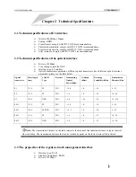
Page 12: ...fferent optical interface parameters please see the table below Optical transceiver Wavelength nm LASER Type Receiver Transmitting Optical Power dBm Overload dBm Receiving Sensibility dBm Transmission Distance Km S1 1310 FP PIN 15 8 8 34 0 25 S2 1310 FP PIN 5 0 8 34 10 60 S3 1550 DFB PIN 5 0 10 36 15 120 SS13 1310 FP PIN 12 3 8 30 0 25 SS15 1550 FP DFB PIN 12 3 8 30 0 25 SS23 1310 FP PIN 5 0 8 32 ...

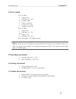
Page 13: ...ption in the table indicates the maximal power consumption of the device when it is operating with no modules The factual power consumption of the device depends on the model and number of modules applied 2 5 Operating environment Operating temperature 0 60 Operating humidity 90 25 2 6 Storing environment Storing temperature 40 80 Storing humidity 5 90 no condensation 2 7 Outline and structure Phy...

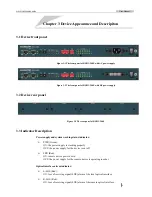
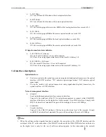
Page 14: ...C831 240E 3 3 Indicator Description Power supply and system working status indicator PWR Green ON the power supply is working properly OFF the power supply for the device is cut off LPR Red ON remote device power down OFF the power supply for the remote device is operating in order Optical interface alarm indicator L LOS Red ON loss of receiving signal LOS alarm at the local optical interface R LO...

Page 15: ... dual strand optical transceivers the optical interface is DSC PC interface TX indicates optical signal output RX indicates optical signal input For device models with optical transceivers using signal strand optical transceivers the optical interface is SC PC interface Network management interface LNK UP Local network management interface or cascade interface Connect to the serial port of the PC ...

Page 16: ...D terminal of the DC power supply are connected in the device and please be sure that one of them is well connected to the protection earth 3 5 Expansion slot description RC831 240E has 4 expansion slots and they are titled SLOT1 SLOT2 SLOT3 and SLOT4 Various expansion sub cards can be inserted into these expansion slots to provide excellent configuration flexibility and to meet different requirem...

Page 17: ...es E1 1 4 occupies E1 5 8 E SUBM 4E1 BL occupies E1 1 4 E SUBM 4E1 BL occupies E1 5 8 LNote When the sub cards in the expansion slot SLOT1 and SLOT3 are sub cards that occupy 4 lines of E1 the expansion slot SLOT2 and SLOT4 can not be used ...

Page 18: ...is turned to the lower side it means that the bit is turned ON When a bit of the switch is turned to the upper side it means that the bit is turned OFF Function setting switch SW1 Definition OFF ON Bit 1 LOOP1 Bit 2 LOOP2 Bit 3 LOOP3 Bit 4 LOOP4 Loopback control switch Bit 5 Loopback point Remote E1 loopback Local E1 loopback Bit 6 Reserved Default status Bit 7 ALS function Disable Enable Bit 8 So...

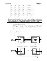
Page 19: ...d in the table above there will be no E1 loopback Bit 5 loopback point selection switch When setting loopback testing using the first 4 bits of SW1 Bit 5 of SW1 is used for selecting the loopback point that is deciding whether the loopback is a remote loopback or a local one The loopback point of the remote E1 loopback and local E1 loopback are shown in the Figure 4 1 and Figure 4 2 respectively B...

Page 20: ...PC The software online upgrade function makes device maintenance and upgrade easier For a RC831 240E device under regular use please do not change the status of the switch and keep its default setting OFF Otherwise the improper setting of the switch may lead to operation abnormity LNote Before electrifying the device please make sure that the status of SW1 Bit 8 is OFF Otherwise the device can not...

Page 21: ...vice 7 ON OFF OFF OFF Local device 8 ON OFF OFF ON Local device 9 ON OFF ON OFF Local device 10 ON OFF ON ON Local device 11 ON ON OFF OFF Local device 12 ON ON OFF ON Local device 13 ON ON ON OFF Local device 14 ON ON ON ON Local device 15 4 1 3 Default settings The factory settings of all DIP switches are OFF This default setting of the device indicates that The device is a remote device The ALS...

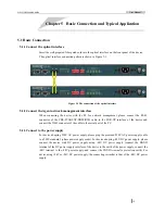
Page 22: ...T DB9F RJ45 cable to the LNK UP interface of the device and connect the DB 9 connector of the cable to the serial port of the PC 5 1 3 Connect to the power supply For device adopting 220V AC power supply please plug the provided 220V AC power supply cable to a 220V standard 3 phase power supply socket For device adopting 48V DC power supply please connect the device with DC power supply using 48V ...

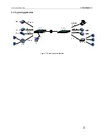
Page 23: ...www raisecom com User Manual 15 5 2 Typical application Figure 5 2 Point to point application ...

Page 24: ...f local remote RC831 240E can be displayed on the network management platform Users can query the working status information and alarm information of the local remote RC831 240E and the sub cards in the expansion slots of the device 6 3 Network management configuration Users can change the function settings completed by DIP switches except for the local remote device address code setting and softw...

Page 25: ...he 4 expansion slots on RC831 240E support various service sub cards Before electrifying the device please make sure that the cable applied matches the sub card model on the device For detailed information please refer to the user manual of the corresponding sub card 7 1 2 Make sure that the fiber applied matches the requirement of the device For RC831 240E M please use multi mode fiber with SC PC...

Page 26: ...er manuals of sub cards 7 2 3 Device electrifying For device using 48V DC power supply please connect the PGND terminal to the protection earth first Before electrifying the power supply cable please connect the 48V terminal with power supply cable with lower electrical potential and connect the BGND terminal with power supply cable with higher electrical potential Please tighten the connection an...

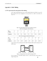
Page 27: ... crystal connector top view Table A 2 Pin arrangement of LNK_UP interface Pin Number 1 2 3 4 5 6 7 8 Definition NC NC IN GND NC NC OUT GND Table A 3 Pin arrangement of the LNK_DWN interface Pin Number 1 2 3 4 5 6 7 8 Definition NC NC OUT GND NC NC IN GND Figure A 2 shows the connecting rule of the LNK UP interface RJ 45 and the serial port of PC DB 9 female Figure A 2 The connection of the device ...

Page 28: ... ON there is problem with the device The optical interface LOF indicator red turns ON Loss of frame alarm of the receiving signal at the optical interface occurs Optical signal has been received but the optical power may be around the critical receiving sensitivity Please measure the receiving optical power and make sure that the TX interface of the optical interface of the remote device has been ...

Page 29: ...ress 2nd Floor South Building of Rainbow Plaza No 11 Shangdi Information Road Haidian District Beijing Postcode 100085 Tel 86 10 82883305 Fax 86 10 82883056 Email export raisecom com http www raisecom com ...

Reviews: