Raisecom
iTN201-R (C) Hardware Description
3 Subcards
Raisecom Proprietary and Confidential
Copyright © Raisecom Technology Co., Ltd.
26
Table 3-14
Interfaces on the iTN200-SUB-4FX
Interface
Type
Purpose
Description
ETH 1–4
SFP
100 Mbit/s Ethernet optical
interface
100Base-FX optical interface
3.5.4 LEDs
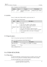
There are 2 LEDs on the iTN200-SUB-4FX, as described in Table 3-15.
Table 3-15
LEDs on the iTN200-SUB-4FX
LED
Status
Description
PWR
Green
Power LED
Green: the power supply is working properly.
Off: the power supply is working improperly.
L:LNK/ACT
1–4
Green
Optical interface working LED
Green: the optical interface is properly connected.
Blinking green: the optical interface is sending/receiving data.
Off: the optical interface is disconnected or improperly
connected.
3.5.5 Specifications
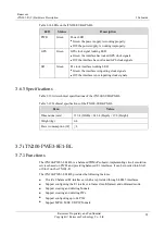
Table 3-16 lists technical specifications of the iTN200-SUB-4FX.
Table 3-16
Technical specifications of the iTN200-SUB-4FX
Parameter
Description
Dimensions (mm)
129.4 (Width) × 243.4 (Depth) × 19.8 (Height)
Weight (kg)
0.18
Power consumption (W)
4
3.6 iTN200-SUB-GPS-BL
3.6.1 Functions
The iTN200-SUB-GPS-BL is a GPS balanced subcard for the iTN201, providing a GPS
antenna for receiving GPS signals and inputting/outputting 1PPS+TOD clock signals.
The iTN200-SUB-GPS-BL provides the following features:


