background image

Raisecom 
ISCOM2600G (A) Series Product Description 

6 Appendix 


Raisecom Proprietary and Confidential 

Copyright © Raisecom Technology Co., Ltd. 

69 


Figure 6-4


Wiring of 100 Mbit/s crossover cable 


Figure 6-5 shows wiring of 1000 Mbit/s crossover cable. 

Figure 6-5


Wiring of 1000 Mbit/s crossover cable 


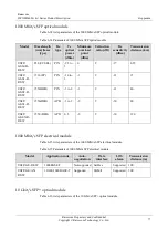
Technical specifications 

Table 6-4 lists technical specifications of the Ethernet cable. 

Table 6-4


Technical specifications of Ethernet cable 

Parameter 

Description 

Name 

CBL-ETH-RJ45/RJ45-D 

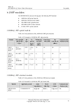
Summary of Contents for ISCOM2600G (A) Series

Page 1: ...ISCOM2600G A Series Product Description Rel_10 www raisecom com...

Page 2: ...cation may be excerpted reproduced translated or utilized in any form or by any means electronic or mechanical including photocopying and microfilm without permission in Writing from Raisecom Technolo...

Page 3: ...nd SFP modules and lists terms acronyms and abbreviations involved in this document Versions The following table lists the product versions related to this document Product name Hardware version Softw...

Page 4: ...t may help you solve a problem or save time General conventions Convention Description Times New Roman Normal paragraphs are in Times New Roman Arial Paragraphs in Warning Caution Notes and Tip are in...

Page 5: ...ommercial release Added the ISCOM2624G 4GE RPS and ISCOM2648G 4GE RPS Issue 05 2016 05 15 Fifth commercial release Added the ISCOM2608G 2GE PWR and ISCOM2624G 4GE PWR Issue 04 2016 04 28 Fourth commer...

Page 6: ...k network access 13 2 2 Residential area broadband access 14 3 System structure 16 3 1 Panels 16 3 1 1 Front panels 16 3 1 2 Rear panels 24 3 2 Interfaces 29 3 2 1 Service interfaces 29 3 2 2 Manageme...

Page 7: ...tions 57 5 1 Overall parameters 57 5 2 Laser safety class 59 5 3 Reliability specifications 60 5 4 EMC indexes 60 5 5 Safety standards 60 5 6 Environmental requirements 61 5 6 1 Storage environment 61...

Page 8: ...3 8 Front panel of ISCOM2624G 4GE PWR AC DC 20 Figure 3 9 Front panel of the ISCOM2624G 4GE RPS AC 20 Figure 3 10 Front panel of the ISCOM2624G 4C AC 21 Figure 3 11 Front panel of the ISCOM2624G 4C D...

Page 9: ...erface 37 Figure 3 36 ISCOM2624G 4GE RPS AC power interface 37 Figure 3 37 ISCOM2648G 4GE RPS AC power interface 38 Figure 4 1 Installing brackets 50 Figure 4 2 Installing cage nuts 50 Figure 4 3 Inst...

Page 10: ...Raisecom Technology Co Ltd viii Figure 6 6 Ground cable 70 Figure 6 7 OT terminal 70 Figure 6 8 DC power cable 71 Figure 6 9 European AC power cable 73 Figure 6 10 American AC power cable 73 Figure 6...

Page 11: ...rmation about 1000 Mbit s SFP electrical module 11 Table 1 11 Ordering information about 10 Gbit s SFP optical module 11 Table 3 1 Service interfaces 30 Table 3 2 Parameters of 10 Gbit s SFP optical i...

Page 12: ...61 Table 5 5 Atmosphere requirements during transport 62 Table 5 6 Atmosphere requirements during operation 62 Table 6 1 Fiber connectors 65 Table 6 2 Wiring of fiber 66 Table 6 3 Wiring of EIA TIA 56...

Page 13: ...irements of all 1000 Mbit s access is designed for the access layer and can be used as aggregation devices for enterprises 1 2 Features Table 1 1 lists features of the ISCOM2600G series switch Table 1...

Page 14: ...ption 18 Zero configuration Support IPv6 zero configuration PoE supported by PoE devices only IEEE 802 3af and IEEE 802 3at Common PoE configurations PD active check PoE scheduling QoS Trust priority...

Page 15: ...KeepAlive RMON LLDP DDM System log Alarm management Fan monitoring Hardware monitoring CPU monitoring Dual system Loopback Ping and Traceroute Performance statistics 1 3 Ordering information 1 3 1 Nam...

Page 16: ...support PoE E RPS redundant powers RPS Support RPS power Do not support RPS power F Power type AC Support AC power supply DC Support DC power supply AC S Support single AC power supply DC S Support si...

Page 17: ...e provides 30 W ISCOM2608G 2GE PWR DC Support eight 10 100 1000 Mbit s RJ45 downlink interfaces Support two 1000 Mbit s Combo interfaces SFP 100 1000Base X interface and RJ45 10 100 1000Base T interfa...

Page 18: ...Support 48 VDC power supply The 24 downlink interfaces have the following features Support PoE for supplying power to the remote PD Support IEEE802 3af and IEEE802 3at Support non standard PDs Support...

Page 19: ...a total power supply of up to 370 W through 24 interfaces each interface provides 15 4 W or 12 interfaces each interface provides 30 W ISCOM2648G 4GE AC Support forty eight 10 100 1000 Mbit s RJ45 dow...

Page 20: ...al 48 VDC power supplies ISCOM2648G 4C AC_DC Support forty eight 10 100 1000 Mbit s RJ45 downlink interfaces Support four 10 Gbit s SFP uplink interfaces it also supports 1000 Mbit s SFP modules Suppo...

Page 21: ...l 4 Table 1 6 lists ordering information about wall mount accessories Table 1 6 Ordering information about wall mount accessories ERP code Component name Quantity 20 08 03 0048 01 ISCOM5104 B wall mou...

Page 22: ...Mbit s SFP electrical module Table 1 8 Ordering information about 100 Mbit s SFP electrical module Model Description USFP FE AN R SW 10 100BASE T auto negotiation Target transmission distance 100 m En...

Page 23: ...ptical module RoHS compliant DDM RoHS compliant 1000 Mbit s SFP electrical module Table 1 10 lists ordering information about the 1000 Mbit s SFP electrical module Table 1 10 Ordering information abou...

Page 24: ...Gbit s Target transmission distance 10 km Tx wavelength 1310 nm Dual fiber SM SFP optical module DDM RoHS compliant USFP 192 S2 SW SFP optical module Transmission rate 10 Gbit s Target transmission di...

Page 25: ...e park network access Residential area broadband access 2 1 Enterprise park network access As shown in Figure 2 1 in the enterprise park network access networking the ISCOM2600G series switch as an ac...

Page 26: ...Enterprise park network access networking 2 2 Residential area broadband access As an access switch the ISCOM2600G series switch can work as a core switch for a small network As shown in Figure 2 2 t...

Page 27: ...ecom ISCOM2600G A Series Product Description 2 Networking applications Raisecom Proprietary and Confidential Copyright Raisecom Technology Co Ltd 15 Figure 2 2 Residential area broadband access networ...

Page 28: ...including the following sections Panels Interfaces Power interfaces LEDs 3 1 Panels Definition of the power supply is listed below AC single AC power supply DC single DC power supply AC DC single powe...

Page 29: ...ice uplink GE interfaces 9 10 7 SNMP interface and Console interface 8 PWR SYS and SNMP LEDs ISCOM2608G 2GE DC Figure 3 2 shows the front panel of the ISCOM2608G 2GE DC Figure 3 2 Front panel of ISCOM...

Page 30: ...link GE interfaces 9 10 7 SNMP interface and Console interface 8 PWR SYS and SNMP LEDs ISCOM2608G 2GE PWR DC Figure 3 4 shows the front panel of the ISCOM2608G 2GE PWR DC Figure 3 4 Front panel of ISC...

Page 31: ...MP SYS and PWR LEDs 6 Mode button PoE mode switching ISCOM2624G 4GE AC Figure 3 6 shows the front panel of the ISCOM2624G 4GE AC Figure 3 6 Front panel of ISCOM2624G 4GE AC 1 Ground terminal 2 Power i...

Page 32: ...the front panel of the ISCOM2624G 4GE PWR AC DC Figure 3 8 Front panel of ISCOM2624G 4GE PWR AC DC 1 Service downlink interfaces 1 24 2 Service uplink GE interfaces 25 28 3 Service uplink SFP optical...

Page 33: ...G 4C AC 1 Ground terminal 2 Power interface 3 Service interfaces 1 28 LEDs 4 Service downlink interfaces 1 24 5 Service uplink interfaces 25 28 6 SNMP interface and Console interface 7 PWR SYS and SNM...

Page 34: ...ervice downlink interfaces 1 48 and LEDs 2 Service uplink SFP optical interfaces 49 52 3 Service uplink GE interfaces 49 52 LEDs ISCOM2648G 4GE RPS AC Figure 3 13 shows the front panel of the ISCOM264...

Page 35: ...terface SYS and PWR1 PWR2 4 SNMP interface and Console interface ISCOM2648G 4C AC DC D Figure 3 15 shows the front panel of the ISCOM2648G 4C AC DC D Figure 3 15 Front panel of the ISCOM2648G 4C AC DC...

Page 36: ...terface and Console interface 3 1 2 Rear panels ISCOM2608G 2GE AC DC Figure 3 17 shows the rear panel of the ISCOM2608G 2GE AC DC Figure 3 17 Rear panel of ISCOM2608G 2GE AC DC ISCOM2608G 2GE PWR AC D...

Page 37: ...he ISCOM2624G 4C PWR DC Figure 3 20 Rear panel of ISCOM2624G 4C PWR DC 1 Ground terminal 2 Power switch 3 Power interface ISCOM2624G 4GE AC DC Figure 3 18 shows the rear panel of the ISCOM2624G 4GE AC...

Page 38: ...Rear panel of ISCOM2624G 4GE PWR DC 1 Ground terminal 2 Power switch 3 Power interface ISCOM2624G 4GE RPS AC Take the AC model for example Figure 3 24 shows the rear panel of the ISCOM2624G 4GE RPS AC...

Page 39: ...SCOM2648G 4GE DC Figure 3 27 shows the rear panel of the ISCOM2648G 4GE DC Figure 3 27 Rear panel of ISCOM2648G 4GE DC 1 Power interface 2 Ground terminal 3 SNMP interface and Console interface 4 SNMP...

Page 40: ...f the ISCOM2648G 4C AC S Figure 3 29 Rear panel of the ISCOM2648G 4C AC S 1 Ground terminal 2 Power interface ISCOM2648G 4C DC S Figure 3 30 shows the rear panel of the ISCOM2648G 4C DC S Figure 3 30...

Page 41: ...ear panel of the ISCOM2648G 4C DC D 1 Ground terminal 2 Power interface ISCOM2648G 4C AC_DC Figure 3 33 shows the rear panel of the ISCOM2648G 4C AC_DC Figure 3 33 Rear panel of the ISCOM2648G 4C AC_D...

Page 42: ...the following adaptive electrical interfaces 10 100 1000BASE T ISCOM2608G 2GE PWR 2 1000 Mbit s Combo interface The SFP interface supports the following SFP optical modules 1000BASE X 100BASE FX The...

Page 43: ...erface supports the following SFP electrical module 1000BASE T The GE interface supports the following adaptive electrical interface 10 100 1000BASE T ISCOM2624G 4C 4 The interface supports the follow...

Page 44: ...electrical module 1000BASE T The GE interface supports the following adaptive electrical interface 10 100 1000BASE T ISCOM2648G 4C 4 The interface supports the following optical modules For 10 Gbit s...

Page 45: ...24 10 100 1000BASE T auto negotiation electrical interface ISCOM2624G 4C 24 10 100 1000BASE T auto negotiation electrical interface ISCOM2624G 4C PWR 24 10 100 1000BASE T auto negotiation electrical i...

Page 46: ...able 3 4 Parameters of 100 Mbit s SFP optical interface Parameter Description Connector type LC PC Optical interface properties Depend on the selected SFP optical module Coding type 4B 5B Working mode...

Page 47: ...45 10 100BASE T adaptive electrical interface You can conduct out of band management on the ISCOM2600G series switch through the SNMP interface RJ45 Console interface Table 3 7 lists parameters of the...

Page 48: ...series switch as shown in Figure 3 34 Figure 3 34 DC power interface Table 3 9 describes the DC power interface Table 3 9 DC power interface Power interface Type Print Usage DC power interface Fence...

Page 49: ...igure 3 35 AC power interface Parameters Table 3 11 lists parameters of the AC power interface Table 3 11 Parameters ofAC power interface Parameter Description Rated input voltage 220 VAC Voltage rang...

Page 50: ...t terminal Specifications Table 3 13 lists parameters of the RPS power interface Table 3 13 Parameters of the RPS power interface Parameter Description Connector type 3 pin Phoenix connector with spac...

Page 51: ...the system is working improperly Blinking green every 1s the system has loaded the configuration file or the device is configured Off the system is working improperly 3 4 2 ISCOM2608G 2GE PWR Table 3...

Page 52: ...working status LED Green the interface is properly connected Blinking green the interface is receiving or sending data Off the interface is disconnected or improperly connected LNK ACT 25 28 Green Com...

Page 53: ...operly connected Blinking green the interface is receiving or sending data Off the interface is disconnected or improperly connected PWR Green Power working status LED Green the power supply is normal...

Page 54: ...he SNMP interface is properly connected Blinking green the SNMP interface is receiving or sending data Off the SNMP interface is disconnected or improperly connected SYS Green System working LED Green...

Page 55: ...orking improperly 3 4 7 ISCOM2624G 4C PWR Table 3 19 lists LEDs on the ISCOM2624G 4C PWR Table 3 20 LEDs on ISCOM2624G 4C PWR LED Status Description ETH LNK ACT Port1 Port24 Green Ethernet interface w...

Page 56: ...SCOM2648G 4GE Table 3 21 LEDs on ISCOM2648G 4GE LED Status Description Port1 Port48 LNK ACT LED Green Ethernet interface working status LED Green the interface is properly connected Blinking green the...

Page 57: ...green the interface is receiving or sending data Off the interface is disconnected or improperly connected Port1 Port48 SPEED LED Green Ethernet interface working rate LED Green the interface works a...

Page 58: ...or sending data Off the interface is disconnected or improperly connected LNK ACT Port49 Port52 Green 10 Gbit s SFP interface working status LED Green the interface is properly connected Blinking gre...

Page 59: ...e LEDs are in PoE status they are the power supply LEDs of the corresponding interfaces When the PoE LEDs are off they are switched to the LNK ACK status displaying the LNK ACK LEDs of the correspondi...

Page 60: ...rdware The ISCOM2600G series switch adopts a 1U cartridge structure It can be easily installed in the following scenarios of a telecom equipment room Cabinet Workbench 4 1 1 Preparing for installation...

Page 61: ...OM2608G 2GE 15 W ISCOM2608G 2GE PWR up to 141 W the PoE interfaces supply power up to 124 W ISCOM2624G 4GE 25 ISCOM2624G 4GE PWR up to 450 W the PoE interfaces supply power up to 370 W ISCOM2624G 4GE...

Page 62: ...ice Therefore you have to install the device to a guide rail or a tray Prepare the guide rail or tray by yourself The ISCOM2648G 4C supports being installed in the rack with steps as below Step 1 Ensu...

Page 63: ...4C horizontally in the rack as shown in Figure 4 4 Figure 4 4 Installing device horizontally in rack Do not lay heavy objects or coverings on the ISCOM2600G series switch Wall mount installation At p...

Page 64: ...ure 4 5 shows how to install brackets to one side Do the same on the other side as shown in Figure 4 5 Figure 4 5 Installing wall mount brackets Step 3 Drill four holes on the wall according to the di...

Page 65: ...2600G series switch Do not stare into the optical interface fiber connector or breakage of fiber directly Connect fiber as below Step 1 Remove the dustproof cover from the SFP optical interface and SF...

Page 66: ...Ethernet cable accordingly Step 2 Insert the RJ45 connector of the Ethernet cable into the Ethernet interface of the ISCOM2600G series switch and insert the other RJ45 connector of the Ethernet cable...

Page 67: ...ies switch is well grounded Step 2 Insert the C13 connector of the AC power cable into the AC power interface on the rear panel tightly Insert the power plug of the AC power cable into the AC power so...

Page 68: ...he ISCOM2600G series switch Step 2 Insert the other end of the RJ45 Console cable into the RS 232 serial interface on a PC or maintenance terminal as shown in Figure 4 14 Figure 4 14 Connecting RJ45 C...

Page 69: ...requirements Standards and protocols 5 1 Overall parameters Table 5 1 lists overall parameters of the ISCOM2600G series switch Table 5 1 Overall parameters of the ISCOM2600G series switch Parameter De...

Page 70: ...GE PWR 5 0 ISCOM2624G 4GE RPS 2 6 ISCOM2624G 4C 2 6 ISCOM2624G 4C PWR 5 0 ISCOM2648G 4GE 4 3 ISCOM2648G 4GE RPS 4 3 ISCOM2648G 4C 4 3 Operating temperature altitude 0 1800 m 0 50 C Operating humidity...

Page 71: ...ode 2 kV in common mode Ethernet electrical interface 6 kV in indoor common mode Table 5 2 lists power input of the ISCOM2648G series switch Table 5 2 Power input of the ISCOM2648G series switch Model...

Page 72: ...he ISCOM2600G series switch should be no longer than 5 minutes Annually system mean repair rate 1 5 MTTR 2 hours MTBF 100000 hours 5 4 EMC indexes The ISCOM2600G series switch designed according to ET...

Page 73: ...Atmosphere requirements during storage Parameter Description Air pressure kPa 86 106 Temperature C 25 to 60 Relative humidity 10 90 Solar radiation W s 1120 Heat radiation W s 600 Wind speed m s 20 W...

Page 74: ...10 90 Solar radiation W s 1120 Heat radiation W s 600 Wind speed m s 20 Waterproof environment When transporting the ISCOM2600G series switch ensure the following prerequisites The package box is inta...

Page 75: ...Network Interface UNI Requirements and Framework MEF Technical Specification MEF 13 User Network Interface UNI Type 1 Implementation Agreement MEF Technical Specification MEF 17 Service OAM Requireme...

Page 76: ...SDH RFC1349 Type of Service in the Internet Protocol Suite RFC2474 Definition of the Differentiated Services Field DS Field in the IPv4 and IPv6 Headers RFC2475 An Architecture for Differentiated Ser...

Page 77: ...Acronyms and abbreviations 6 1 Cables The following cables are used when connecting the ISCOM2600G series switch Cables Ethernet cable Ground cable DC power cable AC power cable RJ45 Console cable 6 1...

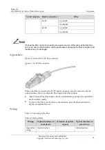
Page 78: ...r connector Figure 6 1 LC PC fiber connector When connecting or removing the LC PC optical connector align the connector with the optical interface and do not rotate the fiber Operate the fiber as bel...

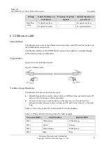
Page 79: ...ve to straight through cable mode and crossover cable mode Appearance Figure 6 2 shows the Ethernet cable Figure 6 2 Ethernet cable Technical specifications The Ethernet cables are divided into two ty...

Page 80: ...te Blue White Blue PIN 6 Orange Green PIN 7 White Brown White Brown PIN 8 Brown Brown Both two RJ45 connectors of the 10 100 1000 Mbit s straight through cable follow EIA TIA568B standard wiring Figur...

Page 81: ...igure 6 4 Wiring of 100 Mbit s crossover cable Figure 6 5 shows wiring of 1000 Mbit s crossover cable Figure 6 5 Wiring of 1000 Mbit s crossover cable Technical specifications Table 6 4 lists technica...

Page 82: ...s you can name it CBL ETH RJ45 RJ45 2m 6 1 3 Ground cable Introduction The ground cable is used to connect the ISCOM2600G series switch to the ground Appearance The ground cable is composed of ground...

Page 83: ...rand copper core conducting wire 1 25 mm2 Model Protective ground round pressed terminal M4 Cross sectional area of the conducting wire 16 15AWG 1 2 1 5 mm2 Length 1 m The ground cable cannot be longe...

Page 84: ...ltage sheathe of cable core pairs 2000 VAC 5min Insulation and withstanding voltage cable core 1500 VAC 5min Certification CCC RoHS Compliant 6 1 5 AC power cable Introduction The AC power cable trans...

Page 85: ...s of European AC power cable Parameter Description Name POL AC European 3 pin C13 connector 0 75mm2 1 5m RoHS Color Outer Black PVC insulation layer Inner Blue N brown L and yellow green stripe E Conn...

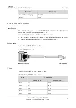
Page 86: ...en debug and maintain it through a PC The connectors at the two ends of the Console cable are as below RJ45 connector connected to the Console interface on the ISCOM2600G series switch DB9 female conn...

Page 87: ...female connector and the RJ45 Console interface on the ISCOM2600G series switch Figure 6 12 Wiring between DB9 female connector and RJ45 Console interface Technical specifications Table 6 11 lists te...

Page 88: ...100 Mbit s SFP optical module Model Wavelength nm Laser type Rx type Tx optical power dBm Minimum overload point dBm Extinction ratio dB Rx sensitivity dBm Transmission distance km USFP 03 M D R SW 13...

Page 89: ...5 to 3 0 9 17 0 55 USFP Gb S1 D R SW 1310 FP PIN 10 to 3 3 9 21 15 USFP Gb S2 D R SW 1550 DFB PIN 3 to 2 3 9 21 40 USFP Gb S3 D R SW 1550 DFB APD 3 to 2 9 9 30 80 USFP Gb EX D R SW 1550 DFB APD 0 5 9...

Page 90: ...Control List ACL A series of ordered rules composed of permit deny sentences These rules are based on the source MAC address destination MAC address source IP address destination IP address interface...

Page 91: ...ast storm caused by the data loop on the Ethernet ring When the link or device on the Ethernet ring fails services can be quickly switched to the backup line to enable services to be recovered in time...

Page 92: ...of QinQ is to add a public VLAN tag to a packet with a private VLAN tag making the packet encapsulated with two layers of VLAN tags The packet is forwarded over the ISP s backbone network based on the...

Page 93: ...o not affect each other 6 4 Acronyms and abbreviations A ACL Access Control List AN Access Node APS Automatic Protection Switching ARP Address Resolution Protocol C CFM Connectivity Fault Management C...

Page 94: ...n Telecommunications Standards Institute I IGMP Internet Group Management Protocol L LLDP Link Layer Discovery Protocol LOS Loss of Signal M MEF Metro Ethernet Forum MTBF Mean Time Between Failure MVR...

Page 95: ...o Ltd 83 SLA Service Level Agreement SP Strict Priority SSHv2 Secure Shell v2 STP Spanning Tree Protocol T TACACS Terminal Access Controller Access Control System TFTP Trivial File Transfer Protocol U...

Page 96: ...s Raisecom Building No 11 East Area No 10 Block East Xibeiwang Road Haidian District Beijing P R China Postal code 100094 Tel 86 10 82883305 Fax 8610 82883056 http www raisecom com Email export raisec...

Reviews: