background image

27

27

Using the wood burning stove

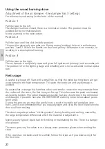
Adjustment of the air damper - the damper has 3 settings

For reference see drawing (in the front of the manual).

Position 1

Pull the lever to the left

.

The damper is almost closed; there is a minimal air intake. This position must be 

avoided during normal operation. 

Notice warning in the next section.

Position 2

Pull the lever until first click (middle position). 

This position gives only secondary air. During normal stoking the lever is set between 

position 1 and 2. When the flames are clear and yellow, the damper is set correctly, i.e. 

resulting in a slow/optimal burning.

Position 3

Pull the lever to the right. 

The air damper is completely open and gives full ignition air (primary) and secondary air. 

The position is for the lighting stage and refuelling and is not used under normal opera-

tion. 

First usage

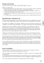
A careful start pays off. Start with a small fire, so that the wood burning stove can get 

accustomed to the high temperature. This gives the best start and any damage is 

avoided.

Be aware that a strange but harmless odour and smoke concoction may emanate from 

the surface of the stove, the first time you fire up. This is because the paint and materi-

als need to harden. The odour disappears quickly, but you should check the ventilation 

and draught, if possible. See also, the IMPORTANT warning notice below about persis-

tent fumes.

During this process you must be careful not to touch the visible surfaces/glass (very 

hot!), and it is recommended that you regularly open and close the door to prevent the 

door seal from sticking. 

The stove may also produce “clicking noises” during heating and cooling, caused by 

the large temperature differences which the material is subjected to.

Never use any type of liquid fuel for kindling or maintaining the fire. There is a danger 

of explosion. 

The stove gets very hot when in use always wear protective gloves when tending the 

stove.

If the stove has not been used for a while, follow the steps as if you were using it for 

the first time.

GB

Summary of Contents for VISIO L Series

Page 1: ...B E D I E N U N G S A N L E I T U N G U S E R M A N U A L M A N U E L D U T I L I S AT E U R B R U K E RV E I L E D N I N G B R U K S A N V I S N I N G K Y T T O H J E G E B R U I K E R S H A N D L E...

Page 2: ......

Page 3: ...l r ggassamleledning og intervalfyring DE Lesen und befolgen Sie die Bedienungsanleitung Zeitbrandfeuerst tte Nur empfohlene Brennstoffe einsetzen UK Fuel types only recommended Follow the installatio...

Page 4: ...Inst llning av spj llet Position 1 Posisjion 1 VISIO 3 positioner af spj ldh n Position 2 Posisjion 2 VISIO 3 positioner af spj ldh ndta Position 3 Posisjion 3 VISIO 3 positioner af spj ldh ndtag Opt...

Page 5: ...h environmentally and economically 1 Effective lighting Use small pieces of wood fir tree and a suit able fire lighter for example paraffined wood wool sawdust Open the air damper so plenty of air is...

Page 6: ...18 INSTALLATION OF FIREPLACE INSERT VISIO L 3 19 INSTALLATION DISTANCES VISIO L 3 21 CONVECTION AIR 22 AIR SYSTEM 24 FUEL 25 DRYING AND STORING 26 REGULATION OF THE SUPPLY AIR TEMPERATURE 26 VENTILAT...

Page 7: ...ood burning stove it is important that you read the manual thoroughly before installing and using it In the case of warranty coverage and for general queries regarding your wood burn ing stove it is i...

Page 8: ...xpansion noise The warranty is invalidated in case of damages caused by overfiring damages caused by external influence and the use of unsuitable fuels non observance of statutory or recommended insta...

Page 9: ...541 660 X 256 X 545 Recommended amount of wood when fuelling kg Distributed on 2 4 logs of wood of approx 30 cm 2 9 Min uptake Min draught Pascal 11 Weight kg approx 293 Efficiency 81 CO emission at...

Page 10: ...102 1638 198 621 541 15 n149 A A B B A A B B 59 n198 116 620 521 539 494 1 413 494 482 0 367 932 5 1596 59 482 607 1765 102 1638 198 621 541 15 n149 A A B B A A B B 59 n198 116 620 521 539 494 1 413...

Page 11: ...581 411 153 481 1765 54 57 102 n149 A A B B 198 169 465 504 1638 26 608 538 634 0 368 931 1581 411 53 481 1765 54 102 A A B B A A B B 544 3 544 3 n198 1088 6 169 465 504 1638 26 608 538 473 473 634 0...

Page 12: ...ghout the room Note however that all exterior surfaces become hot during use so take extreme care Use the insert optimally By installing hot air nozzles and flexible hoses or similar on top of the sto...

Page 13: ...If the stove is fitted in place of an open fire then the chimney should be swept one month after installation to clear any soot falls which may have occurred due to the difference in combustion betwe...

Page 14: ...uld be fitted with a draught stabiliser In which case it is important to ensure that there is a free flow through area of minimum 20 cm when the regulating gate is shut Otherwise the fuel energy may n...

Page 15: ...ack side Dismount the reflector plate and turn it upside down Mount the plate reusing the screws as shown Mounting the reflector plate VISIO L 3 The stove is fitted with a reflector plate Dismount the...

Page 16: ...t the plate to the top of the stove Transport safety Before installing the stove remove the transport safety on VISIO 1 remove 2 screws on the side on VISIO 2 remove 1 screw on the side on VISIO 3 rem...

Page 17: ...nces from the wood burning stove to the panel brick work the internal dimensions of the cassette must be 665 x 1195 x 1950 mm If this is complied with the exterior rear side of the cassette may lie ag...

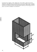
Page 18: ...s Hole dimension for wood burning stove with installation frame A height of 568 mm provides an air gap of 5 mm above the top frame This air gap is necessary because the wood burning stove will expand...

Page 19: ...18 18 GB...

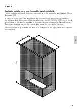
Page 20: ...ances from the wood burning stove to the panel brick work the internal dimensions of the cassette must be 700 x 988 x 1950 mm If this is complied with the exterior rear side of the cassette may lie ag...

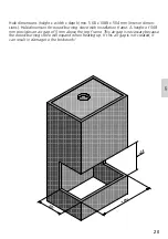
Page 21: ...Holedimension for wood burning stove with installation frame A height of 568 mm provides an air gap of 5 mm above the top frame This air gap is necessary because the wood burning stove will expand wh...

Page 22: ...0 mm Flammable ceiling If the side window is to be flush with the wall the first 250 mm must be made of a non flammable panel There must be at least 100 mm between the wood burning stove and rear pane...

Page 23: ...t for convection air This must be complied with because to avoid the risk of overheating and because of the distance to flammable material Ensure that the wood burning stove can draw in convec tion ai...

Page 24: ...ll the way down to the flue spigot In order to get the most out of your stove guide the warm air out of the convection grate Position the convection grate just below the non flammable top plate The co...

Page 25: ...a check should be made to ensure that the assembly and stove installation has been satisfactory and that there are no leaks in any seals in the appliance and appliance connections to the chimney Ensur...

Page 26: ...the stove is subjected to a larger amount of heat which results in a higher chimney temperature and lower efficiency This can result in the stove and chimney becoming damaged and would void the warra...

Page 27: ...back channels and then emitted as hot scavenging air onto the glass The hot air rinses the glass and keeps it soot free Tertiary air at the back of the burning chamber at the top row of holes ensures...

Page 28: ...burning stove can get accustomed to the high temperature This gives the best start and any damage is avoided Be aware that a strange but harmless odour and smoke concoction may emanate from the surfac...

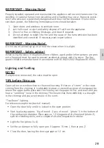
Page 29: ...prevent accidental contact with the stove The fire guard should be manufactured in accordance with BS 8423 2002 Replaces BS 6539 Lighting and fuelling NOTE If airsystem is connected the valve must be...

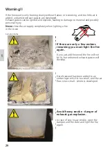
Page 30: ...ftspj ldet helt samt eventuel l ge p klem eller t nd op forfra Advarsel Hvis br ndet kun ulmer eller ryger og der tilf res for lidt luft udvikles der uforbr ndte r ggasser R ggas kan ant ndes og ekspl...

Page 31: ...year During cleaning and care the stove must be cold Prolonged period of non use If the stove is to be left unused for a prolonged period of time then it should be given a thorough clean to remove ash...

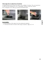
Page 32: ...ove Turn the lock that is positioned above the side of the door The side door can now be opened for cleaning by turning the locking hook in the top and bottom of the door Pull the side glass and clean...

Page 33: ...the stove The ash tray below is removed and emptied into a non combustible container until it has cooled You can dispose of ash with your normal household waste REMEMBER never remove all the ashes fro...

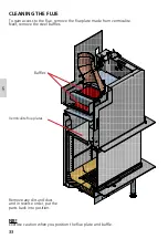
Page 34: ...remove the flue plate made from vermiculite Next remove the steel baffles NB Exercise caution when you position the flue plate and baffle Remove any dirt and dust and in reverse order put the parts ba...

Page 35: ...y could be caused by temperature difference is to small e g due to poorely insulated fluepipe outdoor temperature is high e g in the summer no wind chimney is too short or is on the lee side false air...

Page 36: ...ould ask your chimney sweeper to check the stove and chimney IMPORTANT to ensure safe burning there must be clear yellow flames or clear embers at all times the firewood should not be smouldering If t...

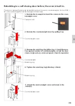
Page 37: ...ews on the coun terweight cover Transport lock 2 Remove the counterweight cover by pulling it up Counterweight cover 3 Remove the retaining ring Allen key 2 5mm Remove the required number of counterwe...

Page 38: ...on both sides 1 Remove the Side Skamol sheet 2 Remove the access panel 3 Unscrew the retaining ring Allen key 2 5mm Remove the required number of counterweights so that the door closes slowly and at a...

Page 39: ...38 38 GB...

Page 40: ...RAIS A S Industrivej 20 DK 9900 Frederikshavn Denmark www rais dk ATTIKA FEUER AG Brunnmatt 16 CH 6330 Cham Switzerland www attika ch...

Reviews: