background image

Digital Video Recorder User Manual 


135 

Step 2


During playback, use buttons 

  or 

  in the playback toolbar to start or stop clipping 

record file(s). 

Step 3


Click 

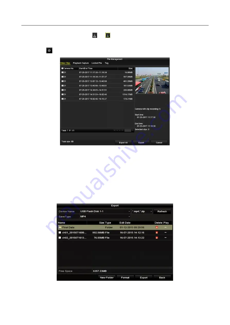
  to enter the file management interface.   


Figure 7-8


Video Clips Export Interface 

Step 4


Export the video clips in playback. Please refer to step5 of 

Chapter 7.1.1 Backing up by 

Normal Video/Picture

 Search for details. 

7.2 Managing Backup Devices 

Management of USB flash drives, USB HDDs and eSATA HDDs 

Step 1


Enter the 

Export

 interface. 


Figure 7-9


Storage Device Management 

Summary of Contents for UDVR Series

Page 1: ...Digital Video Recorder User Manual...

Page 2: ...isclaimer REGARDING TO THE PRODUCT WITH INTERNET ACCESS THE USE OF PRODUCT SHALL BE WHOLLY AT YOUR OWN RISKS OUR COMPANY SHALL NOT TAKE ANY RESPONSIBILITES FOR ABNORMAL OPERATION PRIVACY LEAKAGE OR OT...

Page 3: ...nce 2 This device must accept any interference received including interference that may cause undesired operation EU Conformity Statement This product and if applicable the supplied accessories too ar...

Page 4: ...oduct you must be in strict compliance with the electrical safety regulations of the nation and region Please refer to technical specifications for detailed information Input voltage should meet both...

Page 5: ...ble Power down the unit before connecting and disconnecting accessories and peripherals A factory recommended HDD should be used for this device Improper use or replacement of the battery may result i...

Page 6: ...figuration for each channel including resolution frame rate bit rate image quality etc The minimum frame rate for main stream and sub stream is 1 fps Encoding for both video stream and video audio str...

Page 7: ...n of all channels and 2 ch sudden scene change detection 1U 3MP non real time series support 4 ch line crossing detection and intrusion detection and 16ch 3MP non real time model also support 1 ch sud...

Page 8: ...simultaneous recording Pre record and post record for motion detection triggered recording and pre record time for schedule and manual recording Searching record files and captured pictures by events...

Page 9: ...inking for the VCA alarm VCA detection alarm is supported Supports POS triggered alarm Supports coaxial alarm System will automatically reboot when a problem is detected in an attempt to restore norma...

Page 10: ...wnload locking and unlocking the record files and downloading files broken transfer resume Remote parameters setup remote import export of device parameters Remote viewing of the device status system...

Page 11: ...Basic Configuration in Startup Wizard 49 2 5 Login and Logout 54 2 5 1 User Login 54 2 5 2 User Logout 55 2 6 Resetting Your Password 55 2 7 Adding and Connecting the IP Cameras 57 2 7 1 Activating t...

Page 12: ...iguring Recording and Capture Schedule 92 5 3 Configuring Motion Detection Recording and Capture 96 5 4 Configuring Alarm Triggered Recording and Capture 98 5 5 Configuring Event Recording and Capture...

Page 13: ...Search 133 7 1 3 Backing up Video Clips 134 7 2 Managing Backup Devices 135 Chapter 8 Alarm Settings 137 8 1 Setting Motion Detection 137 8 2 Setting Sensor Alarms 139 8 3 Detecting Video Loss 141 8 4...

Page 14: ...unting 177 11 5 Heat Map 178 Chapter 12 Network Settings 180 12 1 Configuring General Settings 180 12 2 Configuring Advanced Settings 181 12 2 1 Configuring PPPoE Settings 181 12 2 2 Configuring Guard...

Page 15: ...y 210 14 4 Configuring Quota Mode 211 14 5 Configuring Cloud Storage 212 14 6 Configuring Disk Clone 214 14 7 Checking HDD Status 216 14 8 Checking S M A R T Information 217 14 9 Detecting Bad Sector...

Page 16: ...uring General Settings 232 17 2 Configuring RS 232 Serial Port 233 17 3 Configuring DST Settings 234 17 4 Configuring More Settings 234 17 5 Managing User Accounts 236 17 5 1 Adding a User 236 17 5 2...

Page 17: ...s yellow when network connection is functioning properly 2 DIRECTIONS The DIRECTION buttons are used to navigate between different fields and items in menus In the Playback mode the Up and Down button...

Page 18: ...terfaces Universal Serial Bus USB ports for additional devices such as USB mouse and USB Hard Disk Drive HDD Front Panel 2 Figure 1 2 Front Panel Table 1 2 Description of Front Panel No Name Function...

Page 19: ...t to zoom out the image Switches between main and spot video output in live view or playback mode 3 DEF F2 Enters numeral 3 Enters letters DEF Uses the F2 button to change the tab pages Zooms in the i...

Page 20: ...ers letters WXYZ Multi channel display in live view 0 A Enters numeral 0 Shifts the input methods in the editing text field Upper and lowercase alphabet symbols or numeric input 3 DIRECTION Navigates...

Page 21: ...HDD 5 IR Receiver Receiver for IR remote control Front Panel 3 Figure 1 3 Front Panel Table 1 3 Description of Front Panel No Name Function Description 1 POWER ON OFF Power on off switch 2 USB Interfa...

Page 22: ...en network connection is functioning properly 5 DVD ROM Slot for DVD ROM 6 DIRECTION The DIRECTION buttons are used to navigate between different fields and items in menus In Playback mode the Up and...

Page 23: ...o zoom in zoom the PTZ camera The F2 button can be used to cycle through tab pages 4GHI ESC Enter numeral 4 Enter letters GHI Exit and back to the previous menu 5JKL EDIT Enter numeral 5 Enter letters...

Page 24: ...ol Move the active selection in a menu The inner ring will move the selection up and down the outer ring will move it left and right In Playback mode the inner ring is used to jump 30s forward backwar...

Page 25: ...onnection is functioning properly GUARD Indicator turns blue when the device is armed Indicator does not light when the device is disarmed The arm disarm state can be initiated by pressing and holding...

Page 26: ...used to tick checkbox fields In Playback mode it can be used to play or pause the video In single frame Playback mode pressing the button will advance the video by a single frame In Auto switch mode...

Page 27: ...g Numeric button It is also used to turn audio on off in the Playback mode PLAY AUTO Enter the Playback menu Auto scan in the PTZ Control mode ZOOM Zoom in the PTZ camera in the PTZ Control setting A...

Page 28: ...ode it will turn on off PTZ light if applicable In Playback mode it is used to switch between play and reverse play F2 AUX Cycle through tab pages In synchronous playback mode it is used to switch bet...

Page 29: ...camera 8 IR Receiver Receiver for IR remote control 9 DVD R W Slot for DVD R W Front Panel 5 Figure 1 5 Front Panel Table 1 5 Description of Front Panel No Name Function Description 1 POWER ON OFF Pow...

Page 30: ...off when the device is unarmed The arm disarm status can be changed by pressing and holding on the ESC button for more than 3 seconds in live view mode 4 DVD R W Slot for DVD R W 5 Control Buttons DI...

Page 31: ...and USB Hard Disk Drive HDD 7 Front Panel Lock You can lock or unlock the panel by the key 8 Composite Keys ESC Back to the previous menu Press for Arming disarming the device in Live View mode REC S...

Page 32: ...of the camera In Playback mode it can be used to generate video clips for backup Enter exit the folder of USB device and eSATA HDD MAIN SPOT Z OOM Switch between main and spot output In PTZ Control mo...

Page 33: ...the PTZ Control mode In the PTZ Control mode it is used to adjust the iris of the PTZ camera 9 Alphanumeric Buttons Switch to the corresponding channel in Live view or PTZ Control mode Input numbers...

Page 34: ...backward in video files In PTZ control mode it can control the movement of the PTZ camera 11 SLOW DOWN SPEED UP Slow down speed up in playback mode 1 2 IR Remote Control Operations The DVR may also be...

Page 35: ...e 3 REC Button Enter the Manual Record setting menu In PTZ control settings press the button and then you can call a PTZ preset by pressing Numeric button It is also used to turn audio on off in the P...

Page 36: ...rol menu 10 PREV Button Switch between single screen and multi screen mode In PTZ Control mode it is used to adjust the focus in conjunction with the A FOCUS button Troubleshooting Remote Control Make...

Page 37: ...is DVR To use a USB mouse Step 1 Plug USB mouse into one of the USB interfaces on the front panel of the DVR Step 2 The mouse should automatically be detected If in a rare case that the mouse is not d...

Page 38: ...Description of the buttons on the soft keyboard Table 1 8 Description of the Soft Keyboard Icons Icon Description Icon Description Number English letter Lowercase Uppercase Backspace Switch the keyboa...

Page 39: ...UDIO IN RCA connector 3 AUDIO OUT RCA connector 4 VGA DB15 connector for VGA output Display local video output and menu 5 HDMI HDMI video output connector 6 USB Interface Universal Serial Bus USB port...

Page 40: ...T BNC connector for video output 3 AUDIO IN RCA connector 4 USB Port Universal Serial Bus USB port for additional devices 5 HDMI HDMI video output connector 6 VGA DB15 connector for VGA output Display...

Page 41: ...r for alarm output 10 Power Supply 100 to 240 VAC power supply 11 Power Switch Switch for turning on off the device 12 GND Ground 13 LINE IN BNC connector for audio input 14 eSATA Connects external SA...

Page 42: ...o output connector 7 AUDIO OUT RCA connector 8 Network Interface Connector for network 9 RS 485 and Alarm Interface Connector for RS 485 devices T and T pins connect to R and R pins of PTZ receiver re...

Page 43: ...Digital Video Recorder User Manual 42 No Item Description 15 RS 232 Interface Connector for RS 232 devices 16 ALARM OUT Connector for alarm output 17 AUDIO IN for 2U models RCA connector...

Page 44: ...p 1 Check the power supply is plugged into an electrical outlet It is HIGHLY recommended that an Uninterruptible Power Supply UPS be used in conjunction with the device Step 2 Turn on the power switch...

Page 45: ...Password Figure 2 3 Settings Admin Password STRONG PASSWORD RECOMMENDED We highly recommend you create a strong password of your own choosing Using a minimum of 8 characters including at least three o...

Page 46: ...ng password Figure 2 4 Warning Step 3 After the device is activated the Attention box pops up as below Figure 2 5 Attention Step 4 Optional Click Yes to export GUID The Reset Password interface pops u...

Page 47: ...the unlock pattern for device login 2 3 1 Configuring the Unlock Pattern After the device is activated you can enter the following interface to configure the device unlock pattern Figure 2 8 Set Unloc...

Page 48: ...ssfully Figure 2 10 Confirm the Pattern If the two patterns are different you must set the pattern again Figure 2 11 Reset the Pattern 2 3 2 Logging in via Unlock Pattern Only the admin user has the p...

Page 49: ...e normal mode If you have forgotten your pattern you can select the Forget My Pattern or Switch User option to enter the normal login dialog box When the pattern you draw is different from the pattern...

Page 50: ...nfiguration Operating the Setup Wizard Step 1 The Start Wizard can walk you through some important settings of the device If you don t want to use the Start Wizard at that moment click Exit You can al...

Page 51: ...ort GUID to export GUID to the connected USB flash drive for resetting password Refer to Chapter 17 5 3 Editing a User for reference Figure 2 17 Change the Password Step 3 Click Next button and the At...

Page 52: ...utton after you configured the basic network parameters Then you will enter the Guarding Vision interface Configure the Guarding Vision according to your need Refer to Chapter 12 2 2 Configuring Guard...

Page 53: ...ick Next and you can enter the RAID configuration interface Check the checkbox of Enable RAID to take this function into effect Figure 2 23 RAID Configuration Step 8 Click Next button after configurin...

Page 54: ...inactive status you can click the inactive icon of the camera to set the password to activate it You can also select multiple cameras from the list and click the One touch Activate to activate the cam...

Page 55: ...ating the menu and other functions Step 1 Select the User Name in the drop down list Figure 2 27 Login Interface Step 2 Input the Password Step 3 Click OK to log in In the Login interface for the admi...

Page 56: ...ure 2 30 Logout Step 2 Click Logout After you have logged out of the system menu operation on the screen is invalid It is required to input a user name and password to unlock the system 2 6 Resetting...

Page 57: ...ssword Step 3 Input the new password and confirm the password Step 4 Click OK to save the new password Then the Attention box pops up as shown below Figure 2 33 GUID File Imported Step 5 Click OK and...

Page 58: ...amera Purpose Before adding the camera make sure the IP camera to be added is in active status Step 1 Select Add IP Camera from the right click menu in live view mode or go to Menu Camera IP Camera Fo...

Page 59: ...own choosing Using a minimum of 8 characters including at least three of the following categories upper case letters lower case letters numbers and special characters in order to increase the security...

Page 60: ...e list and click to add the camera with the same admin password of the DVR s Or you can click the One touch Adding button to add all cameras with the same admin password from the list Make sure the ca...

Page 61: ...nterface Step 2 You can edit the IP address protocol management port and other information of the IP camera to be added If the IP camera to add has not been actiavated you can activate it from the IP...

Page 62: ...n information of camera Delete the IP camera Play the live video of the connected camera Advanced settings of the camera Upgrade the connected IP camera Security Shows the security status of the camer...

Page 63: ...ure 2 42 Edit IP Camera Channel Port If the connected device is an encoding device with multiple channels you can choose the channel to connect by selecting the channel port No in the drop down list S...

Page 64: ...put Status Step 2 Check the checkbox to select different signal input types HD CVBS and IP If you select HD CVBS four types of analog signal inputs including TVI HD AHD HDCVI and CVBS can be connected...

Page 65: ...ring 5 MP Long Distance Transmission This chapter is only applicable to 5MP non real time series DVR Purpose For 5MP non real time series DVR you can configure 5 MP long distance transmission on the S...

Page 66: ...Digital Video Recorder User Manual 65 Step 4 Click Apply to save the settings...

Page 67: ...Icons Icons Description Alarm video loss tampering motion detection VCA or sensor alarm Record manual record schedule record motion detection or alarm triggered record Alarm Record Event Exception mot...

Page 68: ...P non real time Series S N HDMI2 VGA HDMI1 CVBS Main output Auxiliary output For Live View Output Only 1 or HDMI2 VGA HDMI1 CVBS 2 or or HDMI2 CVBS VGA HDMI1 3 or VGA HDMI1 CVBS HDMI2 For other DVR wi...

Page 69: ...Add IP Camera A shortcut to enter the IP camera management interface For HDVR series only Playback Enter the playback interface and start playing back the video of the selected channel immediately PT...

Page 70: ...2 Switch Main and Aux Output Step 2 Use the mouse wheel to double click on the screen again to switch to the aux output or click Cancel to cancel the operation Step 3 Select the Menu Output Mode to o...

Page 71: ...ble Disable Manual Record Instant Playback Mute Audio on PTZ Control Digital Zoom Image Settings Close Live View Face Detection Information Show Hide VCA Information Capture Picture capture is only ap...

Page 72: ...nly when it is supported by the connected camera Move the mouse onto the Information icon to show the real time stream information including the frame rate bit rate resolution and stream type Figure 3...

Page 73: ...output the VCA information overlay of main output is disabled For the analog cameras if the camera number does not exceed the limit for line crossing detection and intrusion detection the VCA informat...

Page 74: ...wn mute or turning on the audio the screen number for each channel etc Step 1 Go to Menu Configuration Live View General Figure 3 10 Live View General The settings available in this menu include Video...

Page 75: ...in the camera list you would like to display Setting an X means the window will not display any camera 3 You can also click to start live view of all channels in order and click to stop live view of...

Page 76: ...button Diagnose and the results will be displayed on a list You can view the video status and diagnostics time of the selected channels Figure 3 13 Diagnostics Result Connect the camera to the device...

Page 77: ...cedure to set the parameters for PTZ The configuring of the PTZ parameters should be done before you control the PTZ camera Step 1 Go to Menu Camera PTZ Figure 4 1 PTZ Settings Step 2 Select the camer...

Page 78: ...oaxitron Make sure the protocol selected here is supported by the connected camera dome When the Coaxitron protocol is selected all the other parameters like the baud rate data bit stop bit parity and...

Page 79: ...you want the PTZ camera to point to when an event takes place Step 1 Go to Menu Camera PTZ Figure 4 4 PTZ Settings Step 2 Use the directional button to wheel the camera to the location where you want...

Page 80: ...s of the PTZ control Figure 4 5 PTZ Panel General Step 4 Click to enter the preset No in the corresponding text field Step 5 Click the Call Preset button to call it When the Coaxitron camera dome conn...

Page 81: ...hich the PTZ will follow while cycling through the patrol The Duration refers to the time span to stay at the corresponding key point The Speed defines the speed at which the PTZ will move from one ke...

Page 82: ...panel Step 2 Click the General tab to show the general settings of the PTZ control Figure 4 8 PTZ Panel General Step 3 Select a patrol in the drop down list and click the Call Patrol button to call i...

Page 83: ...er of the PTZ Settings interface Or press the PTZ button on the front panel or click the PTZ Control icon in the quick setting bar or select the PTZ option in the right click menu to show the PTZ cont...

Page 84: ...e left limit on the left side of the right limit as well the angle from the left limit to the right limit should be no more than 180 4 2 8 Calling Linear Scan Purpose Follow the procedure to call the...

Page 85: ...ch Park Purpose For some certain model of the speed dome it can be configured to start a predefined park action scan preset patrol and etc automatically after a period of inactivity park time Step 1 C...

Page 86: ...Click the button again to inactivate it 4 3 PTZ Control Panel To enter the PTZ control panel there are two ways supported OPTION 1 In the PTZ Settings interface click the PTZ button on the lower right...

Page 87: ...panel icons Icon Description Icon Description Icon Description Direction button and the auto cycle button Zoom Focus Iris Zoom Focus Iris The speed of the PTZ movement Light on off Wiper on off 3D Zo...

Page 88: ...e install a HDD and initialize it Menu HDD General Figure 5 1 HDD General Step 2 Click Advanced tab to check the storage mode of the HDD Menu HDD Advanced Storage Mode 1 If the HDD mode is Quota pleas...

Page 89: ...ding resolution 5MP non real time series DVR support 5 MP and 4 MP resolution of all the channels The 3 MP signal input is available for channel 1 of 4ch models for channel 1 2 of 8ch models and for c...

Page 90: ...e for main stream is 1 fps Max Bitrate Mode Set the mode to General or Custom Max Bitrate Kbps Select or customize the maximum bit rate for recording Max Bitrate Range Recommended A recommended max bi...

Page 91: ...0 if you set the post record time as 5 seconds it records till 11 00 05 Expired Time The time for keeping the record files in the HDDs once exceeded the files will be deleted The files will be saved p...

Page 92: ...3 Configure the parameters 4 Click Apply to save the settings 5 Optional If the parameters can also be used to other cameras click Copy to copy the settings to other channels The resolution of sub str...

Page 93: ...ou can configure all the parameters on this menu on your demand 5 2 Configuring Recording and Capture Schedule The DVR supports continuous alarm motion motion alarm motion alarm event and POS 1 5U 2U...

Page 94: ...ther motion detection or alarm M A recording triggered by motion detection and alarm POS recording triggered by POS and alarm The POS recording is supported by 1 5U 2U models only Step 2 Choose the ca...

Page 95: ...the time periods cannot be overlapped with each other To enable Event Motion Alarm M A motion or alarm M A motion and alarm and POS triggered recording you must configure the motion detection settings...

Page 96: ...n you enable holiday schedule in Holiday settings See Chapter 5 7 Configuring Holiday Record 6 Click OK to save the settings and return to upper level menu Draw the schedule 1 Click the color icon to...

Page 97: ...you want to copy to Step 5 Click Apply in the Record Schedule interface to save the settings 5 3 Configuring Motion Detection Recording and Capture Purpose Follow the steps to set the motion detectio...

Page 98: ...to set the motion detection for all the area shot by the camera click Full Screen To clear the motion detection area click Clear Figure 5 15 Motion Detection Mask 4 Click and the message box for chann...

Page 99: ...ing or capture Step 1 Go to Menu Configuration Alarm Alarm Input Figure 5 17 Alarm Settings Alarm Input Step 2 Select Alarm Input No Step 3 Input Alarm Name Step 4 Select N O normally open or N C norm...

Page 100: ...ssing detection intrusion detection region entrance detection region exiting detection loitering detection people gathering detection fast moving detection parking detection unattended baggage detecti...

Page 101: ...to Menu Camera VCA Figure 5 21 VCA Settings Step 2 Select a Camera Step 3 Configure the detection rules for VCA events For details see the step 6 in Chapter 10 3 Line Crossing Detection Step 4 Click...

Page 102: ...tinuous capture is prior to the scheduled recording and capture Step 1 Go to Menu Manual Record Figure 5 23 Manual Record Step 2 Enable manual record Click the status icon before camera number to chan...

Page 103: ...e are three different modes for the date format to configure holiday schedule By Month By Week and By Date are selectable 4 Set the start and end date 5 Click Apply to save settings 6 Click OK to exit...

Page 104: ...edundant Recording and Capture Purpose Enabling redundant recording and capture which means saving the record files and captured pictures not only in the R W HDD but also in the redundant HDD will eff...

Page 105: ...elect Camera you want to configure 2 Click More Settings button Figure 5 29 More Settings 3 Check the checkbox of Redundant Record 4 Click OK to save the settings 5 If the encoding parameters can also...

Page 106: ...to save your settings 3 Click OK to back to the upper level menu Step 4 Repeat the above steps to configure more HDD groups Step 5 Choose the Channels which you want to save the record files in the HD...

Page 107: ...Export Normal Figure 5 31 Export Step 2 Select the channels you want to investigate by checking the checkbox to Step 3 Configure the record mode record type file type start time and end time Step 4 Cl...

Page 108: ...ral Figure 5 33 HDD General Step 2 Click to edit the HDD you want to protect Figure 5 34 HDD General Editing Step 3 Set the HDD to Read only Step 4 Click OK to save settings and back to the upper leve...

Page 109: ...ettings Figure 5 36 Advanced Settings Figure 5 37 Advanced Settings Step 2 Click Enable to enable H 264 H 265 for all the analog cameras and the following attention box pops up Figure 5 38 Attention B...

Page 110: ...to 3MP non real time series DVR Task 1 Enabling the 1080P Lite Mode Step 1 Go to Menu Record Advanced Figure 5 40 Advanced Interface Step 2 Check the checkbox of 1080P Lite Mode and click Apply to pop...

Page 111: ...Digital Video Recorder User Manual 110 Figure 5 42 Attention Step 3 Click Yes to reboot the device to activate the new settings or No to restore the old settings...

Page 112: ...channel Choose a channel in live view mode and click the button in the quick setting toolbar In the instant playback mode only record files recorded during the last five minutes on this channel will...

Page 113: ...channel simultaneous playback and channel switch are supported Step 1 Go to Menu Playback Step 2 Check the checkbox of channel s in the channel list and then double click to select a date on the cale...

Page 114: ...s shown in the following figure Figure 6 4 Playback Interface Select the channel s if you want to switch playback to another channel or execute simultaneous playback of multiple channels Figure 6 5 To...

Page 115: ...motion alarm motion alarm motion alarm Playback progress bar use the mouse to click any point of the progress bar to locate special frames The POS overlay function is supported by 1 5U 2U series DVR o...

Page 116: ...e record files You can click Back button to return to the search interface If there is only one channel triggered clicking button takes you to Full screen Playback interface of this channel If several...

Page 117: ...at 10 00 if you set the pre play time as 5 seconds the video plays back from 9 59 55 Post play The time you set to play back after the event For example when an alarm triggered the recording ends at 1...

Page 118: ...ormal Search for the detailed information about searching and playback of the record files Figure 6 9 Interface of Playback by Time Click button to add default tag Click button to add customized tag a...

Page 119: ...t Interface Steps Step 1 Select Tag from the drop down list in the Playback interface Step 2 Choose channels edit start time and end time and then click Search to enter Search Result interface You can...

Page 120: ...Search Purpose The smart playback function provides an easy way to get through the less effective information When you select the smart playback mode the system will analyze the video containing the m...

Page 121: ...Camera Step 2 Configure the required parameters of intrusion detection including area arming schedule and linkage methods Refer to the user manual of smart IP camera for detailed instructions Steps S...

Page 122: ...eo files Filter video files by setting the target characters Show Hide VCA information Step 5 Set the rules and areas for smart search of VCA event or motion event Line Crossing Detection Select the b...

Page 123: ...lable for the motion event type Step 7 Click to search and play the matched video files Step 8 Optional Click to filter the searched video files by setting the target characters including the gender a...

Page 124: ...camera does not support VCA the icon is grey and unavailable For the analog cameras the VCA information includes line crossing detection and intrusion detection For the IP cameras the VCA information...

Page 125: ...ure 6 19 Result of System Log Search Step 3 Choose a log with record file and click button to enter Playback interface If there is no record file at the time point of the log the message box No result...

Page 126: ...n list in the upper left corner of the page to enter the Sub periods Playback interface Step 3 Select a date and start playing the video file Step 4 Select the Split screen Number from the drop down l...

Page 127: ...ist on the top left side The files are listed in the right side list You can click the button to refresh the file list Step 3 Select and click the button to play back it Figure 6 22 Interface of Exter...

Page 128: ...ter Search Result interface Up to 4000 pictures can be displayed each time Step 5 Choose a picture you want to view and click button You can click Back to return to the search interface Figure 6 23 Re...

Page 129: ...1 Go to Playback interface and click button until the speed changes to Single frame Step 2 One click on the playback screen represents playback or adverse playback of one frame You can use button in...

Page 130: ...than one checkboxes to select multiple channels and click to select a date on the calendar Figure 6 26 4 ch Synchronous Playback Interface Step 3 Click to play back the record files reversely 6 2 4 F...

Page 131: ...3 You can view the saved video clips captured playback pictures lock unlock the files and edit the tags which you added in the playback mode Step 4 If required select the items and click Export All or...

Page 132: ...ash drives USB HDDs USB writer SATA writer and e SATA HDD Backup using USB flash drives and USB HDDs Step 1 Go to Menu Export Normal Picture Step 2 Select the cameras to search Step 3 Set search condi...

Page 133: ...Export All to select all the video files for backup and enter the Export interface Figure 7 3 Export by Normal Video Search using USB Flash Drive Step 6 Select the backup device from the drop down lis...

Page 134: ...USB writer or SATA writer has the same operating instructions Please refer to steps described above 7 1 2 Backing up by Event Search Purpose Back up event related record files using USB devices USB f...

Page 135: ...Select video files from the Chart or List interface to export Figure 7 7 Result of Event Search Step 6 Export the video files Please refer to step5 of Chapter 7 1 1 Backing up by Normal Video Picture...

Page 136: ...r the file management interface Figure 7 8 Video Clips Export Interface Step 4 Export the video clips in playback Please refer to step5 of Chapter 7 1 1 Backing up by Normal Video Picture Search for d...

Page 137: ...ce Select a record file or folder in the backup device and click button if you want to delete it Click Erase button if you want to erase the files from a re writable CD DVD Click Format button to form...

Page 138: ...Select a camera you want to set up motion detection Step 3 Set detection area and sensitivity Check checkbox to enable motion detection Use the mouse to draw detection area s or click Full Screen to...

Page 139: ...n click the Copy button to copy the time period settings to other day s Time periods shall not be repeated or overlapped Figure 8 4 Set Arming Schedule of Motion Detection Step 6 Click Linkage Action...

Page 140: ...Enable checkbox and click button to set its alarm response actions Figure 8 6 Set Arming Schedule of Alarm Input Step 3 Select Trigger Channel tab and select one or more channels which will start to...

Page 141: ...PTZ Linking tab and set PTZ linkage of the alarm input Set PTZ linking parameters and click the OK button to complete the settings of the alarm input Check whether the PTZ or speed dome supports PTZ...

Page 142: ...rm for the local alarm input 1 The selected linkage actions include the Full Screen Monitoring Audible Warning Notify Surveillance Center Send Email Upload Captured Pictures to Cloud and Trigger Alarm...

Page 143: ...hedule of the channel Select Arming Schedule tab to set the channel s arming schedule Choose one day of a week and up to eight time periods can be set within each day Or you can click the Copy button...

Page 144: ...overed and take alarm response action s Step 1 Go to Menu Camera Video Tampering Detection Figure 8 12 Video Tampering Interface Step 2 Select a Camera you want to detect video tampering Step 3 Check...

Page 145: ...edule to other days 4 Click the OK button to complete the video tampering settings of the channel Repeat the above steps to finish settings of other channels or click the Copy button copy the above se...

Page 146: ...re Blurred Image Abnormal Brightness and Color Cast Check the corresponding checkbox of the diagnostic type and adjust the threshold of it by dragging the bar The higher the threshold you set the hard...

Page 147: ...Step 6 Click the Apply button to save and activate settings Step 7 Optional you can copy the same settings to other cameras by clicking the Copy button 8 6 Handling Exceptions Purpose Exception settin...

Page 148: ...nt Exception icon when an exceptional event occurs And click the icon to select the detailed event hint for display Figure 8 17 Event Hint Settings Click the icon appears in the live view interface an...

Page 149: ...al monitor HDMI VGA or CVBS monitor displays in full screen the video image from the alarming channel configured for full screen monitoring If alarms are triggered simultaneously in several channels t...

Page 150: ...Email for details of Email configuration Trigger Alarm Output Trigger an alarm output when an alarm is triggered Step 1 Go to Menu Configuration Alarm Alarm Output Step 2 Select an alarm output and se...

Page 151: ...utput Step 4 Repeat the above steps to set arming schedule of other days of a week You can also click Copy button to copy an arming schedule to other days Click the OK button to complete the arming sc...

Page 152: ...ings Step 1 Go to Menu Configuration POS POS Settings Step 2 Select the POS from the drop down list Up to 8 POS units are selectable Step 3 Check the checkbox to enable the POS function Figure 9 1 POS...

Page 153: ...t the POS protocol to Universal Protocol EPSON AVE or NUCLEUS Universal Protocol Click the Advanced button to expand more settings when selecting the universal protocol You can set the start line tag...

Page 154: ...irst Step 6 Select the Connection Type to TCP UDP Multicast RS 232 USB RS 232 or Sniff and click Set to configure the parameters for each connection type TCP Connection When using TCP connection the p...

Page 155: ...USB to RS 232 convertor and the POS must be corresponding to each other e g POS1 must be connected to port1 of the convertor Figure 9 8 USB to RS 232 Settings RS 232 Connection Connect the DVR and th...

Page 156: ...character encoding format from the drop down list 5 Select the overlay mode of the characters to display in scrolling or page mode 6 Select the font size to small medium or large 7 Set the overlay ti...

Page 157: ...o other POS s Figure 9 13 Copy POS Settings 9 2 Configuring Overlay Channel Purpose You can assign the POS machine to corresponding channel on which you want to overlay Step 1 Go to Menu Configuration...

Page 158: ...Menu Configuration POS POS Settings Step 2 Follow the steps in Chapter 9 1 9 2 to configure the POS settings Step 3 Click to enter the alarm settings interface Figure 9 15 Set Trigger Cameras of POS...

Page 159: ...ve steps to set up arming schedule of other days of a week Click the OK button to complete the POS settings of the channel Step 7 Select PTZ Linking tab and set PTZ linkage of the POS alarm Set PTZ li...

Page 160: ...tion detection 1U 3MP non real time series support 4 ch line crossing detection and intrusion detection 16ch models also support 1 ch sudden scene change detection Channels with audio support audio ex...

Page 161: ...ge action and PTZ linking for the face detection alarm Please refer to step 3 to step 5 of Chapter 8 2 Setting Sensor Alarms for detailed instructions Figure 10 2 PTZ Linking Step 5 Click the Rule Set...

Page 162: ...Step 2 Select the camera to configure the VCA You can check the checkbox of Save VCA Picture to save the captured pictures of VCA detection Step 3 Select the VCA detection type to Vehicle Detection St...

Page 163: ...nitoring audible warning etc Step 1 Go to Menu Camera VCA Step 2 Select the camera to configure the VCA You can check the checkbox of Save VCA Picture to save the captured pictures of VCA detection St...

Page 164: ...vity Sensitivity Range 1 100 The higher the value is the more easily the detection alarm can be triggered 3 Click OK to save the rule settings and return to the line crossing detection settings interf...

Page 165: ...figure the trigger channel arming schedule linkage action and PTZ linking for the intrusion detection alarm Step 6 Click the Rule Settings button to set the intrusion detection rules Set the following...

Page 166: ...by specifying four vertexes of the detection region and right click to complete drawing Only one region can be configured You can use the to clear the existing virtual line and re draw it Up to 4 rul...

Page 167: ...n Step 4 Check the Enable checkbox to enable this function Step 5 Click to configure the trigger channel arming schedule linkage action and PTZ linking for the region entrance detection alarm Step 6 C...

Page 168: ...some certain time and a series of actions can be taken when the alarm is triggered Please refer to the Chapter 9 4 Intrusion Detection for operating steps to configure the loitering detection The Thre...

Page 169: ...ich can trigger the alarm The higher the value is the more easily a moving object can trigger the alarm Up to 4 rules can be configured 10 10 Parking Detection Purpose Parking detection function detec...

Page 170: ...etection for operating steps to configure the object removal detection The Threshold 5s 20s in the Rule Settings defines the time of the objects removed from the region If you set the value as 10 alar...

Page 171: ...nd threshold for sound steep rise Sensitivity Range 1 100 the smaller the value is the more severe the change should be to trigger the detection Sound Intensity Threshold Range 1 100 it can filter the...

Page 172: ...he value is the more easily the change of scene can trigger the alarm For the analog cameras the line crossing detection and intrusion detection conflict with other VCA detection such as sudden scene...

Page 173: ...tion Step 3 Select the VCA detection type to PIR Alarm Step 4 Click to configure the trigger channel arming schedule linkage action and PTZ linking for the PIR alarm Step 5 Click the Rule Settings but...

Page 174: ...to the specified conditions Before you start Please refer to Chapter 9 1 Face Detection for configuring the face detection Step 1 Go to Menu VCA Search Face Search Step 2 Select the camera s for the...

Page 175: ...cture item and click to play it You can also click to stop the playing or click to play the previous next file Step 8 If you want to export the captured face pictures to local storage device connect t...

Page 176: ...pecify the start time and end time for searching the matched pictures Figure 11 4 Behavior Search Interface Step 4 Select the VCA detection type from the drop down list including the line crossing det...

Page 177: ...to export the captured pictures to local storage device connect the storage device to the device and click Export All to enter the Export interface Click Export to export all pictures to the storage d...

Page 178: ...p 7 to Step 8 of Chapter 10 1 Face Search for the operation of the search results 11 4 People Counting Purpose The People Counting is used to calculate the number of people entered or left a certain c...

Page 179: ...map is a graphical representation of data represented by colors The heat map function is usually used to analyze the visit times and dwell time of customers in a configured area Step 1 Go to Menu VCA...

Page 180: ...and start heat map statistics and the results are displayed in graphics marked in different colors As shown in Figure 10 8 red color block 255 0 0 indicates the most welcome area and blue color block...

Page 181: ...ti address and Net fault Tolerance Multi address Mode The parameters of the two NIC cards can be configured independently You can select LAN1 or LAN2 in the NIC type field for parameter settings You c...

Page 182: ...d Password should be assigned by your ISP Step 4 Click the Apply button to save the settings Step 5 After successful settings the system asks you to reboot the device to enable the new settings and th...

Page 183: ...Service Terms and Privacy Statement before enabling the service 3 Scan the QR code on the interface to read the Service Terms and Privacy Statement 4 Click OK to save the settings and return to the Gu...

Page 184: ...bsite www guardingvision com and the Guarding Vision Mobile Client User Manual for adding the device to Guarding Vision and more operation instructions 12 2 3 Configuring DDNS Purpose If your DVR is s...

Page 185: ...re 12 7 PeanutHull Settings Interface NO IP Enter the account information in the corresponding fields Refer to the DynDNS settings 1 Enter Server Address for NO IP 2 In the Device Domain Name text fie...

Page 186: ...d use a NTP server that has a time synchronization function such as the server at the National Time Center IP Address 210 72 145 44 If the DVR is set in a more customized network NTP software can be u...

Page 187: ...select Manual as the mapping type you can edit the external port on your demand by clicking to activate the External Port Settings dialog box 1 Click to activate the External Port Settings dialog box...

Page 188: ...ice will send the alarm event or exception message to the host when an alarm is triggered The remote alarm host must have the CMS Client Management System software installed The Alarm Host IP refers t...

Page 189: ...width limit Output Bandwidth After enable the output bandwidth limit input the output bandwidth in the text field The output bandwidth limit is used for the remote live view and playback The default o...

Page 190: ...nter the country host name IP validity and other information 3 Click OK to save the settings OPTION 2 Create the authorized certificate 1 Click the Create button to create the certificate request 2 Do...

Page 191: ...connected to either an intranet or the Internet depending on the location of the e mail accounts to which you want to send notification Additional the Preferred DNS server must be configured Before y...

Page 192: ...hed alarm images The interval is the time between two captures of the alarm images For the IP cameras the alarm images are directly sent as the attached pictures by Email Up to one picture can be sent...

Page 193: ...Purpose You can obtain network connecting status of DVR through the network detection function including network delay packet loss etc 12 3 1 Testing Network Delay and Packet Loss Step 1 Go to Menu Ma...

Page 194: ...t fails to detect the backup device please check whether it is compatible with the DVR You can format the backup device if the format is incorrect Figure 12 22 Export Network Packet Step 3 Click the E...

Page 195: ...message box pops out with other information instead of this one you can click Network button to show the quick setting interface of the network parameters Figure 12 26 Network Parameters Configuratio...

Page 196: ...ser Manual 195 Figure 12 27 Network Stat Interface Step 2 View the bandwidth of Remote Live View bandwidth of Remote Playback and bandwidth of Net Total Idle Step 3 Click Refresh button to get the lat...

Page 197: ...rray that is realized by software You can enable the RAID function on your demand The 1 5U 2U 5MP non real time series DVR support the RAID0 RAID1 RAID5 RAID6 and RAID 10 array types Before you start...

Page 198: ...he RAID function in the Wizard when the device startup please refer to step 7 of Chapter 2 3 2 OPTION 2 Enable the RAID function in the HDD Management Interface Step 1 Enter the Disk Mode configuratio...

Page 199: ...e Chapter 13 1 1 for details 2 As the default array type is RAID 5 please install at least 3 HDDs in you device 3 If more than 10 HDDs are installed 2 arrays can be configured Step 1 Enter the RAID co...

Page 200: ...x to finish the settings Step 6 You can click Array tab to view the information of the successfully created array By default one touch configuration creates an array and a virtual disk Figure 13 5 Arr...

Page 201: ...D 1 RAID 5 RAID6 or RAID 10 select the Physical Disk that you want to configure array If you choose RAID 0 at least 2 HDDs must be installed If you choose RAID 1 2 HDDs need to be configured for RAID...

Page 202: ...take immediate and proper maintenance for the disks so as to ensure the high security and reliability of the data stored in the disk array When there is no disk loss in the array the working status o...

Page 203: ...data Step 1 Enter the Array Settings interface The status of the array is Degraded Since the hot spare disk is configured the system will automatically start rebuilding using it Menu HDD RAID Array Fi...

Page 204: ...d Array Interface Step 3 Select the available physical disk and click OK button to confirm to rebuild the array Step 4 The Do not unplug the physical disk when it is under rebuilding message box pops...

Page 205: ...the data in the array 13 4 Checking and Editing Firmware Purpose You can view the information of the firmware and set the background task speed on the Firmware interface Step 1 Enter the Firmware inte...

Page 206: ...General Figure 14 1 HDD Information Interface You can view the Total Capacity Free Space and Remaining Recording Time of the HDD The algorithm of the Remaining Recording Time is to use average bit rat...

Page 207: ...hus to decrease the power consumption of the device and extend the life of the HDDs Go to Menu HDD Advanced Figure 14 5 Enable HDD Sleeping Check the checkbox of Enable HDD Sleeping by default and the...

Page 208: ...the type to NAS or IP SAN Step 5 Configure the NAS or IP SAN settings Add NAS disk 1 Enter the NetHDD IP address in the text field 2 Click Search to search the available NAS disks 3 Select the NAS dis...

Page 209: ...to add the selected IP SAN disk Up to 8 IP SAN disks can be added Figure 14 9 Add IP SAN Disk 5 After having successfully added the NAS or IP SAN disk return to the HDD Information menu The added NetH...

Page 210: ...face Step 3 Click the Apply button and the following Attention box will pop up Figure 14 12 Attention for Reboot Step 4 Click the Yes button to reboot the device to activate the changes Step 5 After r...

Page 211: ...ent important recorded files from being overwritten when the HDD becomes full in overwrite recording mode When the HDD property is set to redundancy the video can be recorded both onto the redundancy...

Page 212: ...tep 1 Go to Menu HDD Advanced Storage Mode Step 2 Set the Mode to Quota as shown below The DVR must be rebooted to enable the changes to take effect Figure 14 16 Storage Mode Settings Interface Step 3...

Page 213: ...8 Click the Apply button to apply the settings If the quota capacity is set to 0 then all cameras will use the total capacity of HDD for record 14 5 Configuring Cloud Storage Purpose The cloud storage...

Page 214: ...again about 20s later When the Status shows online it indicates the successful registration Step 7 Configure the recording schedule Back to enter the record interface choose a certain camera from the...

Page 215: ...Storage Please configure the event triggered recording schedule and enable the corresponding event type Step 9 Optional You can click the Copy button to copy the cloud storage settings to other camera...

Page 216: ...o the device Step 1 Enter the HDD Advanced Setting interface Menu HDD Advanced Step 2 Click the Disk Clone tab to enter the disk clone configuring interface Figure 14 22 Disk Clone Configuration Inter...

Page 217: ...in case of HDD failure Checking HDD Status in HDD Information Interface Step 1 Go to Menu HDD General Step 2 Check the status of each HDD which is displayed on the list as shown below Figure 14 26 Vie...

Page 218: ...t S M A R T Settings Step 2 Select the HDD to view its S M A R T information list as shown below If you want to use the HDD even when the S M A R T checking is failed you can check the checkbox before...

Page 219: ...the information 14 10 Configuring HDD Error Alarms Purpose You can configure the HDD error alarms when the HDD status is Uninitialized or Abnormal Step 1 Go to Menu Configuration Exceptions Step 2 Sel...

Page 220: ...er Manual 219 Figure 14 30 Configure HDD Error Alarm Step 4 When the Trigger Alarm Output is selected you can also select the alarm output to be triggered from the list below Step 5 Click the Apply bu...

Page 221: ...Name in the text field Step 4 Configure the Display Name Display Date and Display Week by checking the checkbox Step 5 Select the Date Format Time Format Display Mode and the OSD Font Figure 15 1 OSD...

Page 222: ...ettings and back to the OSD Configuration interface Step 8 Click the Apply button to apply the settings 15 2 Configuring Privacy Mask Purpose You are allowed to configure the four sided privacy mask z...

Page 223: ...ed by clicking the corresponding Clear Zone1 4 icons on the right side of the window or click Clear All to clear all zones Figure 15 4 Set Privacy Mask Area Step 6 You can click the Copy button to cop...

Page 224: ...time periods cannot be overlapped with each other Step 4 Select the mode from the drop down list of Mode there are four modes selectable for the analog cameras Standard Indoor Dim Light and Outdoor S...

Page 225: ...d 5 MP 20 fps are selectable The 4 MP 25 fps and 4 MP 30 fps signals are self adaptive for the camera Check Enable Defog to enable the defog function of the selected camera And set the Defog Level fro...

Page 226: ...oes not support them or there is no video signal The parameters are saved to the connected analog camera and are not saved to the DVR The default value of Day to Night Sensitivity Night to Day Sensiti...

Page 227: ...ou can click the Device Info Camera Record Alarm Network and HDD tabs to view the system information of the device Figure 16 1 System Information Interface 16 2 Searching Log Files Purpose The operati...

Page 228: ...Type Step 3 Click the Search button to start search log files Step 4 The matched log files will be displayed on the list shown below Up to 2000 log files can be displayed each time Figure 16 3 Log Sea...

Page 229: ...ice from the drop down list of Device Name Step 8 Click the Export to export the log files to the selected backup device You can click the New Folder button to create new folder in the backup device o...

Page 230: ...configuration file select the file from the selected backup device and click the Import button After the importing process is completed you must reboot the DVR 16 4 Importing Exporting Configuration...

Page 231: ...Select the update file from the backup device Step 4 Click Upgrade to start upgrading Step 5 After the upgrading is completed reboot the DVR to activate the new firmware 16 5 2 Upgrading by FTP Befor...

Page 232: ...16 7 Restoring Default Settings Step 1 Go to Menu Maintenance Default Figure 16 10 Restore Defaults Step 2 Select the restoring type from the following three options Restore Defaults Restore all param...

Page 233: ...Go to Menu Configuration General General Figure 17 1 General Settings Interface Figure 17 2 General Settings Interface Step 2 Configure the following settings Language The default language used is Eng...

Page 234: ...sword every time when you log in to the DVR the Unlock Pattern interface will pop up If you uncheck the checkbox of Enable Password when you log in to the DVR the Unlock Pattern interface will not pop...

Page 235: ...ings Figure 17 4 DST Settings Interface Step 2 Check the checkbox before the Auto DST Adjustment item Or you can manually check the Enable DST checkbox and then you choose the date of the DST period 1...

Page 236: ...HDMI1 VGA and HDMI2 are selectable For other models Auto and HDMI VGA are selectable Enhanced VCA Mode For 5MP non real time series DVR the enhanced VCA mode conflicts with the 2K 4K output and 4 MP...

Page 237: ...the device reboots the output resolution will decrease to 1080p and the 4 MP 5 MP signal input will display no video Step 3 Click Apply to save the settings 17 5 Managing User Accounts Purpose There i...

Page 238: ...ng a minimum of 8 characters including at least three of the following categories upper case letters lower case letters numbers and special characters in order to increase the security of your product...

Page 239: ...The added new user will be displayed on the list as shown below Figure 17 12 Added User Listed in User Management Interface Step 5 You can assign permissions for the added user 1 Select the user from...

Page 240: ...remote client and the device Remote Alarm Control Remotely arming notify alarm and exception message to the remote client and controlling the alarm output Remote Advanced Operation Remotely operating...

Page 241: ...wn below Figure 17 14 User List Step 3 Click to delete the selected user account 17 5 3 Editing a User Purpose For the added user accounts you can edit the parameters Step 1 Go to Menu Configuration U...

Page 242: ...characters including at least three of the following categories upper case letters lower case letters numbers and special characters in order to increase the security of your product And we recommend...

Page 243: ...ort button to export GUID to the USB flash drive for retrieving the forgotten password Then a GUID file will be saved in the USB flash drive Figure 17 17 Export GUID You must input the correct old pas...

Page 244: ...ting Point to Point Protocol PPP frames inside Ethernet frames It is used mainly with ADSL services where individual users connect to the ADSL transceiver modem over Ethernet and in plain Metro Ethern...

Page 245: ...nge a cable to connect again Step 3 Verify Input mode of the monitor is correct Please check the input mode of the monitor matches with the output mode of the device e g if the output mode of DVR is H...

Page 246: ...ecord Parameters Record and set the resolution of Main Stream Event the same as the one of Main Stream Continuous Step 2 Verify the frame rate is real time frame rate Select Menu Record Parameters Rec...

Page 247: ...t Menu Playback and uncheck the checkbox of unnecessary channels Step 4 Check if the fault is solved by the above steps If it is solved finish the process If not please contact the engineer from our c...

Page 248: ...msung SND 50 80P 3 10_130 416 1280 1024 Vivotek FD8134 0107a 1280 800 Bosch Dinion NBN 92 1 P V105004 53 1280 720 Panasonic SP306H Applicati on 1 34 Image Data 1 06 1280 960 Cannon VB H41 0 Ver 1 0 0...

Page 249: ...15AD 100 to 240 VAC 12 V 1 5 A 18 W 5 5 2 1 10 0000200878 Shenzhen Transin Technologies Co Ltd MSA C2000IC12 0 24P DE 12 V 2 A 0000201935 MOSO Technology Co Ltd ADS 24S 12 1224GPG CE 100 to 240 VAC 12...

Reviews: