10
Figure 2: Cable Diagram Amplifier, Radio, Loudspeaker
Page 1: ...Verst rker Germanium Two 2 Kanal Verst rker Art Nr 271065 Bitte vor Beginn der Arbeiten Einbauanleitung sorgf ltig lesen AIV GmbH Co KG Tatschenweg 1 74078 Heilbronn Telefon 07131 5953 0 Telefax 07131...
Page 2: ...hen Arbeiten am Fahrzeug Nehmen Sie Ihr Fahrzeug nicht in Betrieb bevor alle Komponenten des Lautsprechersystems und des Verst rkers fest und sicher eingebaut sind Lose Teile k nnen im Falle eines pl...
Page 3: ...ono Br ckenschaltung 16 16 Bild 7 Lautsprecheranschlu Tri Mode 17 17 Bild 8 Hinweise zur Stromversorgung 18 Festlegung des zentralen Massepunktes 18 Prinzipschaltplan Zentraler Massepunkt 20 Bild 9 Ga...
Page 4: ...sein Installieren Sie den Verst rker nur im Wageninnenraum oder im Kofferraum Installieren Sie den Verst rker nicht im Motorraum Der Verst rker darf keinem Druck ausgesetzt sein und nicht verdeckt wer...
Page 5: ...ung Bei Anschluss eines externen Kondensators immer die Anweisungen in dessen beigelegter Anleitung beachten Wir haften nicht f r Sch den die durch den unsachgem en Gebrauch externer Stromversorgungss...
Page 6: ...ch der Europ ischen CE Norm Technische Daten Ausgangsleistung Stereo 4 2 x 140 Watt rms Ausgangsleistung Stereo 2 2 x 215 Watt rms Ausgangsleistung Mono 4 1 x 430 Watt rms Gesamtklirrfaktor THD N 0 02...
Page 7: ...reo max 10 mm 10 Schalter f r Hochpass HPF Tiefpass LPF oder Normal FULL 11 Ausgangsbuchsen LINE OUT f r Folgeverst rker 12 Eingangsbuchsen LOW INPUT f r den Signaleingang vom CD Radio 13 Regler Gain...
Page 8: ...ktronik und zum sofortigen Erl schen der Garantieleistungen Rotes Kabel mit Querschnitt von 16 mm bis 35 mm direkt an den Pluspol der Batterie oder an den zentralen Pluspunkt der HiFi Anlage anschlie...
Page 9: ...te Bei einer permanenten St rungsanzeige liegt ein Defekt im Ger t vor Verst rker bitte zur Instandsetzung einsenden Anschlu LOW INPUT Verst rkereingang An den Cinchbuchsen LOW INPUT 12 R Rechts und L...
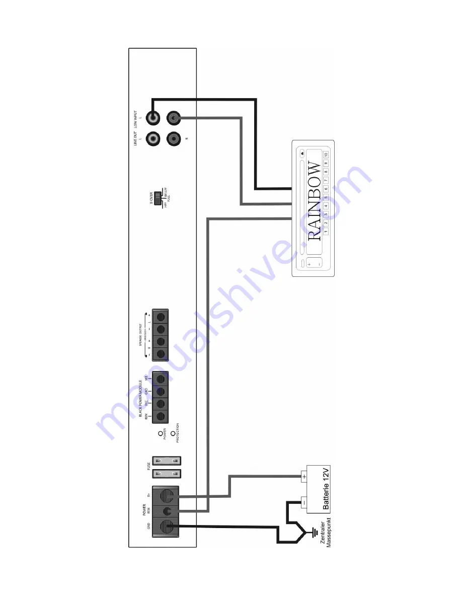
Page 10: ...10 Bild 2 Anschlu schema Verst rker Autoradio Lautsprecher...
Page 11: ...ztrennung erfolgt ausschlie lich in den Passivweichen des jeweiligen Lautsprechersystems Daher ist diese Betriebsart f r alle Lautsprecherarten und Lautsprechersysteme geeignet bei welchen die Frequen...
Page 12: ...s deutlich Die Kickbass Leistung des Lautsprechers wird dabei keinesfalls eingeschr nkt sonder wird im Pegel noch erweitert Zus tzlich wird der Lautsprecher thermisch und mechanisch stark entlastet Sc...
Page 13: ...dert werden Einstellungen am PHASE Regler 15 solange ver ndern bis die Basswiedergabe optimal ist Achtung Der Phasenschieber funktioniert nur wenn sich der Schalter X OVER 10 auf der Position BP LPF b...
Page 14: ...ick Panel siehe hierzu Brosch re KickBass Forver oder im Subwoofer Betrieb als Tiefpass mit Subsonic Schalter X OVER 10 hierzu in Stellung BP LPF bringen und Grenzfrequenz des Hochpasses Frequenz ab d...
Page 15: ...unbedingt auf gleiche Polarit t Phasengleichheit geachtet werden Beim Verwechseln der Polarit t Phase geht die Stereobasis sowie die Tieftonwiedergabe durch Phasenausl schung verloren siehe Bild 6 Ach...
Page 16: ...Cinchbuchsen verteilt Die Anschlu impedanz des Lautsprechers darf bei Monobetrieb nicht unter 4 betragen um die kritische 2 Grenze der Verst rkerimpedanz nicht zu unterschreiten Ein 2 Lautsprecherans...
Page 17: ...Woofer des Lautsprechersystems auf der Heckablage sinkt bei tiefen Frequenzen aufgrund des begrenzenden Membranenhubes auf ein Minimum der elektrischen Belastbarkeit ab wenn keine Schutzma nahmen f r...
Page 18: ...Spannungsabfalls am langen Kabelweg vorzeitig verzerren clippen Dieses kann durch gro en Kabelquerschnitt und Minimierung der bergangswiderst nde an den Anschlu stellen verhindert werden Entsprechend...
Page 19: ...bereich Die Endstufen werden bereits im Leerlauf oder im kleinsten Leistungsbereich stark durch hochfrequente St rfrequenzen erhitzt Die Eingangsvorstufe des Verst rkers kann nicht zwischen Musik und...
Page 20: ...Bil Bild 9 Prinzip Schaltplan Prinzip Schaltplan Zentraler Massepunkt aler Massepunkt 20...
Page 21: ...enn Fehler durch unsachgem e Montage Transportschaden mechanische Besch digung oder durch Fremdeingriff entstanden sind Unf lle h here Gewalt oder andere von Rainbow nicht zu verantwortende Ursachen i...
Page 22: ...ermanium Two 2 Channel Amplifier Part No 271065 Please read installation manual carefully before beginning installation AIV GmbH Co KG Tatschenweg 1 74078 Heilbronn Germany Telephone 49 7131 5953 0 Te...
Page 23: ...of its products Work to Vehicle Do not begin operation of vehicle before all components of the loudspeaker system and the amplifier are firmly and securely in place Many parts when unsecured can beco...
Page 24: ...Bridged 16 16 Figure 7 Loudspeaker Connection Tri Mode 17 17 Figure 8 Power Provision Indications 18 Determining Central Ground 18 Principal Connection Diagram Central Ground 20 Figure 9 Warranty Ter...
Page 25: ...ll the amplifier only in the car interior or trunk Do not install the amplifier in the engine compartment The amplifier should not be placed under pressure or covered Make certain that no foreign part...
Page 26: ...possible use the included fuse Always follow the accompanying instructions when connecting an external condenser We do not accept responsibility for damage caused by the inappropriate use of an exter...
Page 27: ...nce proof certified by CE Technical Data Output Power Stereo 4 2 x 140 Watt rms Output Power Stereo 2 2 x 215 Watt rms Output Power Mono 4 1 x 430 Watt rms Total Harmonic Distortions THD N 0 02 Signal...
Page 28: ...ional 8 Loudspeaker connections 2 channel Stereo max 10 mm 10 Switch for high pass HPF broadband FULL or band low pass BP LPF operation 11 Signal output LINE OUT for subsequent amplifiers 12 Input soc...
Page 29: ...ing of the warranty Attach red cable with diameter of 16 mm2 to 35 mm2 directly to the positive terminal of the battery or the central positive point of the HiFi unit and run to the amplifier Make abs...
Page 30: ...hould be relocated to a well ventilated area A persistent indication of trouble suggests that a defect in the equipment is present The amplifier should be sent in for repair INPUT Connection Amplifier...
Page 31: ...10 Figure 2 Cable Diagram Amplifier Radio Loudspeaker...
Page 32: ...e Frequency separation takes place exclusively in the passive crossovers of the respective loudspeaker systems This mode of operation is therefore suitable for all kinds of loudspeakers and loudspeake...
Page 33: ...mance of the loudspeaker is in no way reduced but rather the capabilities are improved Additionally the loudspeaker thermal and mechanical capabilities are strengthened Switch X OVER 10 should be adju...
Page 34: ...nged by adjusting the potentiometer PHASE 15 Adjust settings on the PHASE controller 15 until the bass rendition is optimal Caution The phase shifter functions only when the switch X OVER 10 is in the...
Page 35: ...he door or kick panel see brochure KickBass Forever or in subwoofer mode as low pass with subsonic Set switch X OVER 10 to BP LPF and cut off frequency of the highpass frequency from which the loudspe...
Page 36: ...close attention to like polarity phase balance Switching the polarity phase balance results in the stereo basis and bass rendition being lost through phase cancellation Fig 6 Caution The loudspeaker...
Page 37: ...during mono operation The connection impedance of the loudspeakers during mono operation may not fall below 4 in order that the critical minimum connection impedance of 2 is maintained A 2 loudspeaker...
Page 38: ...the woofer of the rear deck loudspeaker system will fall at low frequencies because of the limits on power handling set by the cone excursion when no security measures for the lower frequency range ha...
Page 39: ...ifier can distort when long cable lengths cause a premature voltage drop This can be prevented by using a cable with a large diameter and minimizing the transition resistance at the connection points...
Page 40: ...Output is already heated in the no load operation or in the smallest capacity range by high frequency distortion The preliminary input stage of the amplifier cannot differentiate between music and dis...
Page 41: ...20 Figure 9 Principal Central Ground Diagram Battery Main fuse Potential equipotential Regulator Generator housing Connection if required Central plus point Central g round point...
Page 42: ...m does not exist if defects resulted from inappropriate assembly transport damage mechanical damage or foreign interference Accidents forces of nature or other causes which can be answered for in part...