


ESP-SMTe Controller
33
Troubleshooting
Alarms and Notes
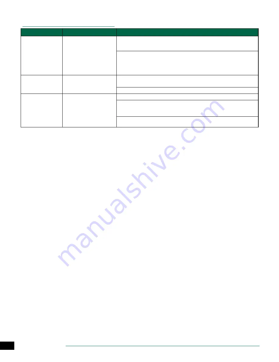
Symptom
Possible Cause
Correction
ALARM 1 on Display
Screen.
Sensor Pod Communication Error
If there are no obvious wiring or connection problems, press the Reset button located on the back
of the front panel. After the front panel is reset, communication with the Sensor Pod is usually
established within 15 seconds.
Check the status LED lights on the Sensor Pod by removing the wiring access cover with a
screwdriver (underneath the Sensor Pod):
Solid - Good Communication
Blinking- No Communication (reset front panel)
Off- No Power (check wiring)
ALARM 2 on Display
Screen.
No Temperature Data Error
Press the Reset button located on the back of the front panel. If the alarm does not clear, see if
there is a wiring or connection problem.
If the alarm is unable to be cleared, the Sensor Pod may need to be replaced.
ALARM 3 on Display
Screen.
Short Circuit Error
See if there is a wiring or connection problem.
Fix any wiring problem between the controller and the identified zone or valve.
NOTE:
A shorted Master Valve will prevent any zone that is activated with the Master Valve from
watering. Always repair a shorted Master Valve before fixing zone wiring.
Sprinkler valves can also be shorted internally. Disconnect the valve from the wire to the controller
and run the Short Circuit Test (turn the dial to
Special Features
) to see if the short is cleared.
FCC Part 15
This equipment has been tested and found to comply with the limits for a Class
B digital device, pursuant to Part 15 of the FCC Rules. These limits are designed
to provide reasonable protection against harmful interference in a residential
installation.
This equipment generates, uses, and can radiate radio frequency energy and,
if not installed and used in accordance with the instructions, may cause harm-
ful interference to radio communications. However, there is no guarantee that
interference will not occur in a particular installation.
If the equipment does cause harmful interference to radio or television recep-
tion, which can be determined by turning the equipment off and on, the user is
encouraged to try to correct the interference by the following measures:
• Reorient or relocate the receiving antenna.
• Increase the separation between the equipment and receiver.
• Connect the equipment into an outlet on a circuit different from that to which
the receiver is connected.
• Consult the dealer or an experienced radio/TV technician for help.
• Changes or modifications not expressly approved by Rain Bird Corporation
could void the user’s authority to operate the equipment.
• This product was FCC certified under test conditions that included the use
of shielded I/O cables and connectors between system components. To bin
in compliance with FCC regulations, the user must use shielded cables and
connectors and install them properly.
• This class B digital apparatus meets all requirements of the Canadian Interfer-
ence Causing Equipment Regulations.
Cet appareil Numérique de la classe B respecte toutes les exigences du Règle-
ment sur le matériel brouilleur du Canada
Safety Information
CAUTION: This appliance is not intended for use by persons (including
children) with reduced physical, sensory or mental capacity, or lack of
experience and knowledge unless they have been given supervision or
instruction concerning use of the appliance by a person responsible for
their safety. Children should be supervised to ensure that they do not play
with the appliance.
c
c
WARNING: Special precautions must be taken when valve wires
(also known as station or solenoid wires) are located adjacent to, or
share a conduit with other wires, such as those used for landscape
lighting, other “low voltage” systems or other “high voltage” power.
Separate and insulate all conductors carefully, taking care not to
damage wire insulation during installation. An electrical “short”
(contact) between the valve wires and another power source can
damage the controller and create a fire hazard.
c
c
WARNING: All electrical connections and wiring runs must com-
ply with local building codes. Some local codes require that only a
licensed or certified electrician can install power. Only professional
personnel should install the controller. Check your local building
codes for guidance.
c
b
NOTE: Date and time are retained by a lithium battery which must
be disposed of in accordance with local regulations.
CAUTION: Use only Rain Bird approved accessory devices. Unapproved
devices may damage the controller and void warranty. For a list of com-
patible devices go to: www.rainbird.com