


Raider 40 HP
SECTION 3
Owner’s Manual
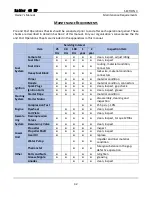
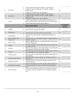
Maintenance Requirements
48
T
IMING
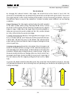
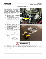
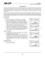
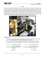
Timing is set by adjusting the Ball Joint Connector and Nut located on the Advancer Link Rod. The Ball
Joint Connector attaches to the Ball Joint on the underside of the Coil Plate Assembly. Timing is measured
in degrees with the scale located on the Coil Plate Assembly. The scale markings indicate 5° increments,
beginning with -10° and ending with 25°. The measurement is read from the scale at the point where the
seam (fitting line) of the crank case and block coincide. To make adjustments, remove the Ball Joint
Connector from the Coil Plate. Adjust the length of the Advancer Link Rod so that the ignition timing
match mark lines up with the fitting line of the crankcase and block and lock it with a nut.
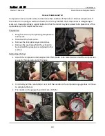
Timing Settings
•
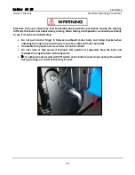
B.T.D.C.: Turn the throttle grip to the fully open position. Verify the timing match mark is (22°)
+/- 2° with the fitting line of the crankcase and block, adjust as required.
•
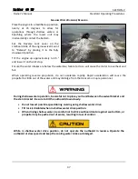
A.T.D.C.: Turn the throttle grip to the fully closed position. Confirm that the ignition timing
match mark is (0°) +/-2° with the fitting line of the crankcase and block, adjust as required.
B.T.D.C. 22°
A.T.D.C. 0°
Summary of Contents for Raider 40 HP
Page 1: ...i ...
Page 2: ...ii This page intentionally left blank ...
Page 65: ...56 APPENDICES ...
Page 69: ...60 Notes and Discrepancies ...
Page 72: ...This page intentionally left blank ...
Page 73: ......


