background image

Page 5 of 22

IN063 Rev.D 0120

3 Saber Way, Ward Hill, MA 01835   |   radonaway.com

1.3.   Unpacking and Locating System Components


1.3.1.  Unpack All System Components


Remove all packing material and discard appropriately away from the work area.


1.3.2.  Locate All Components


Check to ensure all components are intact and included in shipment.(See Figure 5 and 8)


Included component list (may vary with order):


• Tank Assembly with Solenoid Assembly


• Control Panel* and Float Switches


• Submersible Pump**


• Jet Pump and Bladder Tank Assembly***


• Brass – Bypass Assembly, Pump Brass, and Tank Brass****


• Installation Kit – Manual, Pressure Gauge, etc.


* Model 321 does not come equipped with a control panel


** Mounted internally on 433-S50 and 433-S75 Systems, not supplied with 433 and 321 Systems.


*** Pump packages are sold separately on 321 and 433 Systems, and will vary with the order.    


      Bladder Tanks are sold separately.


**** Sold separately on 321 and 433 Systems. Standard systems are equipped for a ¾” 

                   plumbing connection. 1” plumbing connection is available on 433 Systems only (Not 433          

                  433-S50 or 433-S75). Please specify plumbing connection requirements when ordering. 


      Bypass Assembly is integral on 433-S50 Systems Only. 

1.4.  

 Use Qualified Technicians

A Licensed Plumber, Electrician, Contractor and/or Certified Water Treatment Specialist may be 

required to install the AIRaider

TM

 System in accordance with the installation instructions. All wiring 

must be performed in accordance with the National Fire Protection Association’s (NFPA)”National 

Electrical Code, Standard #70”-current edition for all commercial and industrial work. All wiring 

must be performed by a qualified and licensed electrician. Check your Local and State Code and 

Licensing requirements. Failure to follow the instructions may lead to poor system performance and/

or possible system damage.

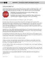
The Installation must comply with all applicable Local and State Codes and 

NFPA National Electrical Code, Standard #70!

1.5.   Full Water Test

A full Water Sample Analysis must be performed to determine the quality of the water that requires 

treatment. In many water supplies, contaminants other than radon are present and may need to be 

pre-treated in order for the AIRaider

TM

 to work properly. The AIRaider

TM

 System is only effective for 

the removal of  radon and some other VOC’s. The Aeration Process employed by the AIRaider

TM


System and other radon removal systems can worsen problems due to iron or manganese contaminants in 

the water supply. 

For optimal removal of radon or other VOC’s, other contaminants such as iron or 

manganese must be removed before the water supply enters the AIRaider

TM

 System. Installation of 

a sediment filter is highly recommended as a pre-treatment of the water supply. The filter should 

be routinely cleaned or replaced. 

FAILURE TO REMOVE OTHER CONTAMINANTS INCLUDING SEDIMENT CAN REDUCE 

SYSTEM  EFFECTIVENESS AND MAY RESULT IN SYSTEM DAMAGE ,  COMPONENT MALFUNCTION, 

PROPERTY DAMAGE, AND PERSONAL INJURY.

PRE-INSTALLATION

1

Summary of Contents for AIRaider 321

Page 1: ...AIRaider Instruction Installation Manual All Residential Small System Models IN063 Rev D 0120 3 Saber Way Ward Hill MA 01835 radonaway com ...

Page 2: ...E 18 4 1 Six Month Service recommended 18 4 2 AnnualService required 19 4 3 Recommended Addiional Service 19 5 TROUBLE SHOOTING 20 LIMITEDWARRANTY 21 APPENDICES A 1 Pump Specification 433 S50 Systems pump model 20DOMO5121 1 insert Figure 1 a b c Typical Systems 433 S 433 321 6 Figure 2 Pump Bypass Assembly 433 321 7 Figure 3 Installed System 433 321 8 Figure 4 Plumbing Installation 433 S50 9 Figur...

Page 3: ...f the AIRaiderTM System there are 5 items to be considered They are 1 Safety 2 Installation Site Requirements 3 Inspection of System Components 4 Necessity for Qualified Technicians 5 Knowledge of all Contaminants in the Water 1 1 Safety Matters Safety is the most important step in the installation process Never perform any step of the installation that you are not qualified to perform i e Electri...

Page 4: ...he following is needed Garden Hose Five Gallon Bucket A Stop Watch or Watch with a Second Hand Or A Water Flow Meter Household water use must be discontinued during the following flow rate test Mid Range Flow Rate Test 1 Attach garden hose to the drain connection on the base of the Well Pressure Tank 2 Open the drain valve and run water for 15 minutes 3 After 15 minutes check the pressure gauge on...

Page 5: ...ructions All wiring must be performed in accordance with the National Fire Protection Association s NFPA National Electrical Code Standard 70 current edition for all commercial and industrial work All wiring must be performed by a qualified and licensed electrician Check your Local and State Code and Licensing requirements Failure to follow the instructions may lead to poor system performance and ...

Page 6: ... System Start up 8 System Check 9 Install Overflow Protection and Alarm Prior to Use It is recommended that a Flood Stop P N 28276 sold separately be installed prior to use of this system to provide point of leak detection whereby a motorized ball valve will automatically shut off the system and prevent potential overflows should debris clog a shut off valve A basement water alarm also should be i...

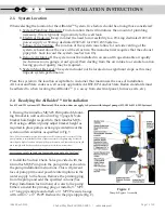
Page 7: ...anel furnace exits etc 2 2 Readying the AIRaiderTM for Installation For 433 and 321 systems 433 Illustrated This section does not apply to Systems with integral pumps 433 S50 433 S50X Systems 1 If using the Grundfos MQ3 45 Pump attach Mount ing Bracket to wall as shown in Fig 3 page 8 Note bracket hole height is specific to the Grundfos MQ3 45 If using a different pump adjust bracket height as req...

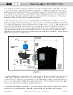
Page 8: ...e MQ3 45 Pump Fittings required may vary with pump used The optional Bladder Tank has a MNPT threaded connection A tee will be required if the bladder tank is installed otherwise an elbow may be used at the same location To facilitate removal of pump for service a quick disconnect sharkbite as illustrated or pipe union is recommended on the pump side of the required System Outlet Valve normally op...

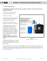
Page 9: ...r or gate valve in the water line to the house is required for balancing the system flow A Bladder Tank minimum capacity 5 gallons is required for 433 S50 Systems 20gal min for 433 S50X WARNING Bladder Tank must be supported by hanger attached to wall or joist 6 Making sure the Bypass valve is open and Inlet and Outlet Valves are closed slowly open the water main valve and check for leaks 7 Slowly...

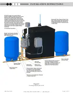
Page 10: ...Page 10 of 22 IN063 Rev D 0120 3 Saber Way Ward Hill MA 01835 radonaway com INSTALLATION INSTRUCTIONS 1 2 Figure 5 Plumbing Installation 433 S50X ...

Page 11: ... Receptacle from the Jet Pump Power Cord without connecting the wires thus exposed to the jet pump inside the Jet Pump Electrical Enclosure Always secure the Jet Pump Enclosure Cover after making electrical connections 3 On 433 S50X units only the installer may need to disconnect the Armored Cable supplied in order to install the Pressure Switch The Armored Cable may require trimming to the desire...

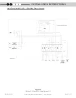
Page 12: ...Page 12 of 22 IN063 Rev D 0120 3 Saber Way Ward Hill MA 01835 radonaway com Figure 6 AIRaider 321ND and 433ND Wiring Diagram 115V 321ND and 433ND 115V 1Ph 60Hz Power Supply INSTALLATION INSTRUCTIONS 1 2 ...

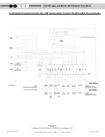
Page 13: ... D 0120 3 Saber Way Ward Hill MA 01835 radonaway com Figure 7 AIRaider 433 S50 X ND and 321 S50X Wiring Diagram 115V 433 S50 X ND and 321 S50X with HP Submersible Pump 115V 1PH 60Hz Power Supply INSTALLATION INSTRUCTIONS 1 2 ...

Page 14: ... 4 The vent line must be pitched back toward the system to prevent condensation build up 5 Cement all fittings in a manner that ensures no leakage will occur Be certain to use cement that is suitable for potable water applications 6 Install weather cap on top of the vent line This cap should not restrict air flow and must prevent rain snow and other contaminants from entering the vent line Failure...

Page 15: ... intake line from the pipe connection on the blower to the location selected for air intake Note A rubber coupling or similar means to disconnect the intake line from the is recommended 3 Connect the Air Filter to the vent line using the proper reducer coupling If the air intake is located outside the filter or intake must be mounted high enough off the ground to prevent the drawing in of snow wat...

Page 16: ...ollow pump manufac turer s instructions to prime other external pumps The normal operating range is nominally 40 PSI 60 PSI but will vary Pressure Switches on 433 S50 433 S50X factory set at 38 PSI 55 PSI approx Do Not Attempt to Adjust the Pressure on 433 S50 or 433 S50X Systems as this may result in the pump not shutting down as it attempts to reach too high a set pressure This problem may not o...

Page 17: ... the end of the preset delay Release the lower float d While the tank is still filling lift the upper float water in flow should stop and the blower will remain running Release the upper float Pushing down the lower float on 433 S50 and 433 S50X Systems will shut off the pump e Remember to shut off any open taps within the residence 4 Replace the lid and secure with the fasteners provided With the...

Page 18: ...ommended The following procedures should be followed to maintain the AIRaiderTM Check and or clean the blower air intake filter Check and or clean any filters or strainer installed on the inlet line to the AIRaiderTM In installations with particularly high levels of sediment cleaning of filters may be required more frequently Check and clean inlet screen on pump Using a wet dry vac clean sediment ...

Page 19: ... dry vac clean sediment from bottom of aeration tank if necessary Clean if necessary tank and diffusers of all mineral build up Chlorinate tank and lines by pouring cup of chlorine into the first aeration chamber Check all control panel connections and electrical components blower pump timer fuses etc for proper operation Check float switches for proper operation Inspect vent line for possible obs...

Page 20: ... if applicable and clean if necessary Check fuse in control panel Check breaker at electrical panel Replace jet pump if necessary Reset jet pump as described in System Start up p 17 Check bladder tank Replace jet pump and or bladder tank as necessary Clear sediment strainers on faucets Clear pump inlet screen water injector Replace pump if necessary Check fuses in control panel Replace timer if ne...

Page 21: ...way RADONAWAY SPECIFICALLY DISCLAIMS ANY WARRANTY OF FITNESS FOR A PARTICULAR PURPOSE THERE ARE NO WARRANTIES WHICH EXTEND BEYOND THE DESCRIPTION ON THE FACE HEREOF THERE IS NO WARRANTY OF MERCHANTABILITY ALL OTHER WARRANTIES EXPRESSED OR WRITTEN ARE NOT VALID In order to obtain service under this warranty the consumer must contact the installer or dealer where the unit was purchased The installer...

Page 22: ...3 SaberWay Ward Hill MA 01835 Phone 800 355 0901 Fax 978 521 3964 E mail sales spruce com ...

Reviews: