10
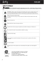
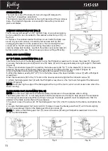
INSTALLING/REPLACING PINLESS (PLAIN END) BLADES (Fig. 1~4)
1. Turn the scroll saw OFF and unplug from the power source.
2. Loosen the tension by lifting the quick tension release lever
(1-Fig .1).
3. Tilt the table to the 0˚ bevel setting and lock into position with
the table locking knob (5-Fig. 1).
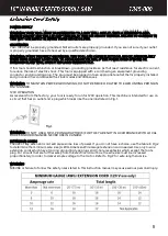
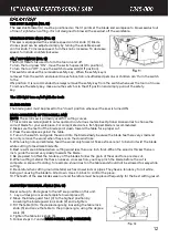
4. Loosen the table insert locking lever (2) and pull out the quick
release table insert (3)(Fig. 2).
NOTE: Pull out the table insert for a better view of the lower blade
holder.
4. Install the blade (4) through the access hole (5) in the table with
teeth pointing down.(Fig. 2)
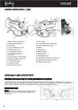
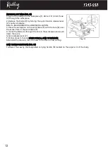
5. Insert the blade (4) into the lower blade holder slot (6), then
tighten the lower blade holder
locking knob
(7) . (Fig. 3)
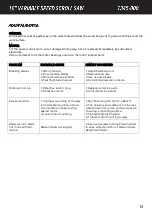
Note: Insert the T-shaped hex wrench to the lower blade holder
locking knob. Rotate the T-shaped hex wrench Clockwise/counter-
clockwise to tight/loosen the blade. See picture (A) below.
6. Apply slight downward pressure against the upper arm (8) when
installing the blade into the upper blade holder. (Fig. 3)
7. Insert the other end of the blade (4) into the upper blade holder
slot (9), and then tighten the upper blade holder
locking knob (10).
(Fig. 3)
Note: Insert the T-shaped hex wrench to the upper
blade holder locking knob. Rotate the T-shaped hex
wrench Clockwise/anticlockwise to tight/loosen the
blade. See picture (B).
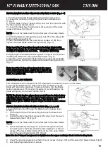
ADJUSTING BLADE TENSION
Push the Blade tension release lever (11) downward. Increase the tension on the blade
by turning the Blade tension release lever (11) clockwise until the
blade will “sing” when plucked. To reduce tension, turn the Blade
tension release lever (11) counterclockwise. To avoid breaking the
blade during use, do not over tighten (Fig. 4).
NOTE: The blade tension release lever must always be down before
adjusting blade tension. Lift the blade tension release lever upward
only during blade-changing operations. If the blade is over-
tightened, it will be difficult to push down the blade tension release
lever.
INSTALLING/REPLACING PIN END BLADES (Fig. 1, 2, 4, & 5)
Loosen the tension by lifting up the Blade tension release lever.
(1-Fig .1)
1.
Tilt the table to the 0° bevel setting and lock the bevel knob
(5-Fig. 1).
2.
Loosen the table insert locking lever (2) and pull out the quick
release table insert (3). (Fig. 2)
NOTE: Pull out the table insert for a better view of the lower blade
holder
3.
Install the blade by inserting one end of it through the access
hole (5-Fig. 2) in the table. Hook the lower blade pin in the pin
recess of the lower blade holder (12) and then the upper blade
pin of the upper blade holder (13). (Fig. 5)
Note: Use the T-shaped hex wrench to tight/loosen the upper and lower blade holder locking knob.
4.
Check the pins are properly located in the pin recess of upper (13) and the lower (12) blade holders (Fig.5).
5.
See “Adjusting blade tension” above.


