background image

Installation Guide

2

Configuration recommendations

Standard SCM configurations come without SFP or XFP transceivers installed. To protect the internal 
components of the SCM, transceivers or filler plugs must be installed in all empty sockets:

ƒ

The Base Ethernet configuration supports up to four SFP transceivers and one XFP transceiver, with 
filler plugs installed in unused sockets.

ƒ

The Fabric Ethernet configuration supports up to four XFP transceivers, with filler plugs installed in 
unused sockets.

For a list of tested and qualified transceivers and filler plugs, see the Support section of the RadiSys 
Web site at 

www.radisys.com

Transceiver installation

SFP and XFP transceivers can be installed on the SCM 
at any time, but RadiSys recommends performing the 
installation before the SCM is installed in the shelf. 

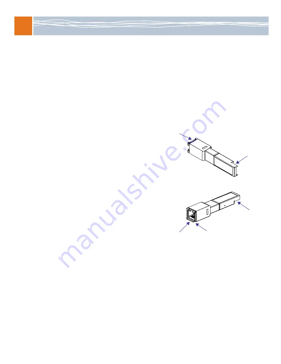
The illustration shows the correct orientation for 
inserting an SFP transceiver. The SFP you use may vary 
in appearance depending on manufacturer, but should 
follow the same insertion guidelines. Use these same 
guidelines when inserting XFP transceivers as well.

1. Follow ESD precautions and make sure you are 

adequately grounded. 

2. Remove the transceivers and the SCM from their 

antistatic bags. 

3. On the SCM’s faceplate, remove the filler plugs 

from the sockets in which you are installing the 
SFP or the XFP transceivers. For sockets not being 
used, keep the filler plugs in place to protect the 
internal components of the board. 

4. Make sure the transceiver’s bale (the latch on the 

cable side of the transceiver) is in the closed 
position. This ensures that the transceiver will snap 
into position when inserted into the socket. 

5. How you insert the transceiver into the socket depends on the SCM’s orientation: 

ƒ

If the SCM is oriented vertically, insert the transceiver so the connector side is on the left. 

ƒ

If the SCM is oriented horizontally, insert the transceiver so the connector side is down.

6. Once inserted into the socket, carefully slide the transceiver until its connector is fully seated and 

snaps into position. 

7. Repeat the above steps for each transceiver being installed. 

8. For transceivers with cable plugs installed on their cable side, keep the plugs in place until you are 

ready to plug cables into the transceivers. The cable plugs protect the internal components of the 
transceivers.

Cable side

Connector 
side is on left

Vertical insertion

Connector 

side is down

Bale in 
closed position

Cable side 

Horizontal insertion

Summary of Contents for PROMENTUM ATCA-2210

Page 1: ...14 or ATCA 6016 shelf A 9 pin D shell to RJ 45 serial port cable shipped with the SCM A standard crossover Ethernet cable Adequate ventilation for the shelf Install SFPs or XFPs on the SCM The SCM comes with sockets for small form factor pluggable SFP and 10 Gigabit small form factor pluggable XFP transceiver modules If SFPs and XFPs are installed they can provide external connections to the Ether...

Page 2: ...e adequately grounded 2 Remove the transceivers and the SCM from their antistatic bags 3 On the SCM s faceplate remove the filler plugs from the sockets in which you are installing the SFP or the XFP transceivers For sockets not being used keep the filler plugs in place to protect the internal components of the board 4 Make sure the transceiver s bale the latch on the cable side of the transceiver...

Page 3: ...side is on the left and the flat smooth side is on the right If the SCM is oriented horizontally insert the filler plug so the recessed side is on the bottom and the flat smooth side is on the top SFP filler plug installation If the SCM is oriented vertically insert the filler plug so the connector side and retaining clip are on the left If the SCM is oriented horizontally insert the filler plug s...

Page 4: ...stallation of the SCM in the non RadiSys shelf you must disable the SCM s on board Shelf Manager 1 Install the SCM in the shelf on page 5 2 Disable the Shelf Manager on the SCM on page 10 3 Verify switch operation on page 7 ____ ____ ____ Removed from a non RadiSys shelf and reinstalled in a RadiSys shelf Pre removal configuration required Before you remove the SCM from the non RadiSys shelf you m...

Page 5: ...the SCM If the SCM does not slide easily make sure you are inserting the SCM into the correct slot and that it is aligned properly 5 Once the SCM is inserted all the way into the shelf simultaneously close both ejector latches inward This seats the SCM s connectors into the shelf s backplane The hot swap H S LED light flashes until the SCM is fully powered Once powered the LED light turns off If t...

Page 6: ... the prompt 5 Verify that you receive a welcome message and a prompt showing ATCA 2210 Important If the SCM has been installed in a non RadiSys shelf you may receive a DEBUGMODE prompt rather than the ATCA 2210 prompt If this occurs disable the SCM s on board Shelf Manager See Disable the Shelf Manager on the SCM on page 10 for more information Connect to the Ethernet maintenance port 1 Connect a ...

Page 7: ...e enabled If needed press the space bar to view more of the list 4 Proceed to the applicable section or step To enable all ports see Enable all ports on page 8 To enable only specific ports see Enable specific ports on page 8 To leave all ports disabled continue with step 5 5 Enter the exit command to return to the ATCA 2210 prompt If you are asked to save changes enter y for yes or n for no If yo...

Page 8: ...up configuration Note If the SCM includes the optional Procelerant CE3100 COM Express module you may need to perform some additional port configuration procedures See the ATCA 2210 Switch and Control Module Reference for more information 3 Enter the exit command to return to the ATCA 2210 prompt 4 Enter the exit command to log off the SCM 5 If you have two SCMs installed repeat these steps on the ...

Page 9: ...s configuration is saved as the startup configuration Base Ethernet switch interfaces ATCA 6000 backplane slots s 0 p 1 6 9 14 ATCA 6006 backplane slots s 0 p 3 6 ATCA 6014 backplane slots s 0 p 1 6 9 14 ATCA 6016 backplane slots s 0 p 1 7 10 16 Front panel optical s 1 p 5 9 Internal ports s 2 p 1 3 4 RTM s 3 p 5 8 or p 5 6 depends on SCM configuration Base Ethernet switch internal ports 2 1 The l...

Page 10: ...s command to exit the platform management CLI exit 5 If you have two SCMs installed repeat these steps on the other SCM Disable the Shelf Manager on the SCM By default the SCM is configured to function in a RadiSys shelf For an SCM to operate in a non RadiSys shelf you must disable the Shelf Manager on the SCM 1 Connect the included serial port cable by plugging one end into the RJ 45 serial port ...

Page 11: ... Enter ShMC Mode Enable 0 Disable 1 Enter 1 to disable the on board Shelf Manager The menu prompt displays upon completion of the process 13 To verify the on board Shelf Manager is disabled enter 41 14 The following text displays Get SCM ShMgr Mode Enter address in hex Enter the same host address you entered for step 11 If the on board Shelf Manager is disabled this message displays SCM ShMgr Mode...

Page 12: ...e Enter key and verify you get a login prompt Enter root at the prompt 5 To determine the version of SCM s on board Shelf Manager enter the following at the ATCA 2210 prompt resys_debug h 6 After determining the version number enter the appropriate command 7 Once the software tool has completed its initialization the host address is displayed Make a note of this address for an upcoming step Typica...

Page 13: ...hip with a factory installed basic software package Once the SCM is installed and depending on your organization s needs you may choose to change the BIOS setting or install an operating system and drivers See the ATCA 2210 Switch and Control Module Reference for instructions on performing such procedures Where to go from here See the ATCA 2210 Switch and Control Module Reference for detailed info...

Page 14: ...sit the RadiSys Web site at www radisys com for product information and other resources Downloads manuals release notes software etc are available via the Technical Support Library product links at www radisys com support or the product pages at www radisys com products ...

Reviews: