background image

RadioLink Electronic Ltd

www.radiolink.com

10

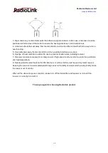
3. Big models may contain metal parts that influence signal emission. In this case. antennas should be
positioned at both sides of the model to ensure the best signal status in all circumstances.
4. Antennas should be kept away from metal conductor and carbon fiber at least half inch away and no
over bending.
5. Keep antennas away from motor, ESC or other possible interference sources.
6. Sponge or foam material is advised to use to prevent vibration when installing receiver.
7. Receiver contains some electronic components of high-precision. Be careful to avoid strong vibration
and high temperature.
8. Special vibration-proof material for R/C like foam or rubber cloth is used to pack to protect receiver.
Keeping the receiver in a well sealed plastic bag can avoid humidity and dust, which would possibly make
the receiver out of control.

When all the above steps are complete, please turn off the transmitter and repower on to test if the
receiver is correctly bind with it.

Thank you again for choosing RadioLink product.

Summary of Contents for R8FG

Page 1: ...R8FG FHSS INSTRUCTION MANUAL Two way Transmission PWM PPM SBUS Signal Supported 8 channel Receiver with Integrated Gyro ...

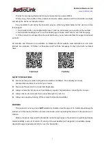
Page 2: ...cebook and YouTube homepage to stay tuned with our latest news Facebook YouTube SAFETY PRECAUTIONS Never operate your model during adverse weather conditions Poor visibility can cause disorientation and loss of control of your model Never use this product in a crowd and illegal area Always ensure the trim levers at 0 and battery properly charged before connecting the receiver Always check all serv...

Page 3: ...Signal and RSSI 4 2 2 Telemetry of model battery and receiver voltage 5 3 Child ID 6 4 Working Modes 7 4 1 Working mode setting 8 4 2 LED Indicator Color in Different Working Modes 8 5 Gyro Introduction 8 5 1 Gyro Function 8 5 2 Gyro Enable 8 5 3 Gyro Reverse 8 5 4 Gyro Sensitivity Adjustment 9 6 R8FG Specifications 9 7 Note of Antenna Installation 9 ...

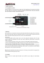
Page 4: ...close distance between the transmitter and receiver may cause a signal block which leads to unsuccessful binding or signal loss Turn on both the transmitter and the receiver and then the LED of R8FG will start flashing slowly There is a black binding button ID SET on the side of the receiver Press the button for more than 1 second and release the LED will flash quickly indicating the binding proce...

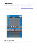
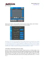
Page 5: ...d via https www radiolink com rc4gs_firmware If you are using RC8X RC6GS V3 RC6GS V2 RC4GS V3 or RC4GS V2 the default firmware supports telemetry function Power on RC8X and R8FG receiver The signal and other telemetry information will be displayed in the home page of RC8X if the binding is successful and the telemetry cable is connected correctly RC8X home page 2 1 Telemetry of Signal and RSSI Pow...

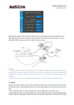
Page 6: ...The larger the absolute value of the RSSI value is the weaker the signal is For example the signal when the RSSI value is 90dBm is weaker than the signal when the RSSI value is 75dBm 2 2 Telemetry of model battery and receiver voltage Besides the return of receiver voltage model battery voltage maximum up to 8S lithium battery 33 6V can also be returned in real time Users can personalize the warni...

Page 7: ...ecting to the battery cannot reverse polarity connect or it will lead to the wrong voltage value telemetry 2 Telemetry port is only used to model voltage telemetry It can not be used to power the receiver 3 Child ID RC8X can bind with multiple receivers When RC8X and multiple receivers have been bound successfully and RC8X and all successfully paired devices are turned on at the same time There ar...

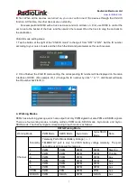
Page 8: ... corresponding ID number will be displayed on the main interface of RC8X For example ID_1 Change the ID number by click or click Reset will make the ID number back to ID_0 4 Working Modes R8FG has a built in gyroscope which can output not only PWM signals but also PPM and SBUS signals There are four working modes including ordinary PWM mode SBUS mode Gyro mode and Gyro SBUS mode The channel signal...

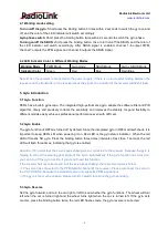
Page 9: ...o different models easily achieves professional performance even with drift cars 5 2 Gyro Enable The gyro function of R8FG is turned off by default Since the integrated gyro in R8FG will self check it is important to keep R8FG still when powering it on Red LED is the gyro status indicator When the red LED off means NO gyro Press the binding button three times intervals of less than 1 second the re...

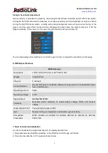
Page 10: ... sensitivity on this page 6 R8FG Specifications 7 Note of Antenna Installation In order to maximize the signal transmission it s greatly advised that 1 Keep antennas as straight as possible or the effective control range will reduce 2 Keep the two antenna in 90 angle as shown below R8FG Receiver Dimensions L W H 35 24 13 5mm 1 38 0 94 0 53 Weight 10 5g 0 37oz Channel 8 channels Control Distance Gr...

Page 11: ...Sponge or foam material is advised to use to prevent vibration when installing receiver 7 Receiver contains some electronic components of high precision Be careful to avoid strong vibration and high temperature 8 Special vibration proof material for R C like foam or rubber cloth is used to pack to protect receiver Keeping the receiver in a well sealed plastic bag can avoid humidity and dust which ...

Reviews: