


Radio Systems, Inc.
•
601 Heron Drive
•
Logan Twp., New Jersey 08085
(856) 467-8000
•
Fax (856) 467-3044
•
www.studiohub.com
For Assy:
12072
Rev: 10/04
For Assys:
DA12-DC
DA6-DC
Rev: 01/05
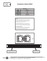
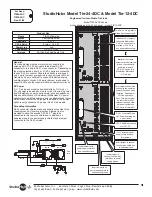
St Model DA12-DC & Model DA6-DC
Single and Dual Stereo Distribution Amplifier
Left
Right
Out 1 - RIGHT
Out 4 - LEFT
Out 1 - LEFT
Out 4 - RIGHT
Out 2 - RIGHT
Out 5 - LEFT
Out 2 - LEFT
Out 5 - RIGHT
Out 3 - RIGHT
Out 6 - LEFT
Out 3 - LEFT
Out 6 - RIGHT
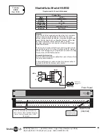
Out 1
Out 2
Out 3
In 1a
In 1b
Out 4
Out 5
Out 6
+/- 15V DC Power
connector for pass-
thru power on dual
Hub, deal DA or dual
Mixer panels
Insert jumpers in
both headers to
/- DC on
output cable to
power StudioHub
DC-Link devices
Note - DC not
available on outputs
2 & 5
Insert jumper under
output headers to
connect RJ-45
shielded to Hub
electrical ground
Green LED s indicate
audio presence at
+24 dB
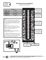
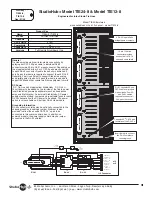
+/- 15V DC Power
connector for pass-
thru power on dual
Hub, dual DA or dual
Mixer panels
LED s indicate presence
of +/- 15V DC
Insert jumpers in
both headers to
mono input
Insert jumper under
output headers to
connect RJ-45
shielded to Hub
electrical ground
Jumper right and
center pins (on both
headers) to increase
input level sensitivity
by +10 dB. Jumper
left and center pins
(on both headers) to
increase level
sensitivity by +20 db
Parallel stereo audio
inputs are provided
for program loop
through
Insert jumper in
header to connect
Hub electrical to
chassis ground
Insert jumper in
header to connect
input connector
RJ-45 shields to Hub
electrical ground
Insert jumpers in
both headers to
/- DC on
output cable to
power StudioHub
DC-LINK devices
Note - DC not
available on outputs
2 & 5
Add a second section
of DA6-DC here to
create a DA12-DC
12 output DA (or add
any St
board to create a
combo product.)
br


