Radio Systems, Inc.
CT2002 Manual
Page 1
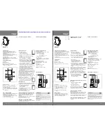
Serial Time of Day Connections from CT2002 and GPS Models
Note:.software/hardware.kit.is.available.(Radio.Systems.part.#.CT-SYNC).
to.update.Windows.PC.clocks.from.your.CT-2002.serial.data.stream
GN
D
SE
RI
AL
O
UT
-
SE
RI
AL
O
UT
+
GN
D
ST
AR
T S
W
ITC
H
ST
OP
S
W
ITC
H
RE
SE
T S
W
ITC
H
M
OD
E S
W
ITC
H
GN
D
TIM
E C
LO
SU
RE
1
TIM
E C
LO
SU
RE
2
TIM
E C
LO
SU
RE
3
TIM
E C
LO
SU
RE
4
GN
D
DO
WN
TI
ME
C
LO
SU
RE
AT
“0
”
TO
H
RE
SE
T I
NP
UT
RJ
-4
5
OU
T
RJ
-4
5
IN
9V DC IN
MODEL CT-2002 DESKTOP P art No. 14409
SE
RI
AL
IN
+
SE
RI
AL
IN
-
RJ
-4
5
SH
IEL
D
TO
G
ND
Logan T ownship, New J ersey USA
1-856-467-8000 • www .radiosystems.com
1 2 3 4 5 6 7 8
BA
CK
DI
P
SW
ITC
HE
S
(U
P
IS
ON
)
SE
RI
AL
D
AT
A
OU
T +
SE
RI
AL
D
AT
A
OU
T -
GR
OU
ND
ST
AR
T S
W
ITC
H
ST
OP
S
W
ITC
H
RE
SE
T S
W
ITC
H
M
OD
E S
W
ITC
H
GR
OU
ND
AH
EA
D
DC
T
O
CL
OC
KS
10
H
z
TO
C
LO
CK
S
GR
OU
ND
N.
O.
CO
NT
AC
T
N.
O.
CO
NT
AC
T
AN
TE
NN
A
15V DC IN
1
Hz
O
UT
TO
IMPULSE
DRIVER
TO
ANALOG
CLOCKS
TOP
OF HOUR
CLOSURE
MODEL CT-2002 GPS P art No. 14411
Connect up to 32 serial slav e clocks in Ï dasiy chainÓ
configuration. Use twisted pair 24A WG cable
(preferrably shielded.) The last clock in chain must be
terminated with a 120
Ω
resistor (or use the termination
DIP switch on the CT2002 Lar ge Display.)
Serial daisy chain
connectivty may also
be via CAT-5 cable and
RJ-45 conectors.
Use a standard 568B
ethernet patch cable
(all wires conecting
straight thru pin to pin)
or for custom made
cables observe pinouts
to right.
CT-
2002 4” & 2”
SE
RI
AL
IN
PU
T
TE
RM
IN
AT
IO
N
RJ-45 OUT
RJ-45 IN
GND
+15V DC IN
RJ
-4
5
SH
IE
LD
TO
G
ND
1 2 3
4 5
6 7 8
9 10
111213
1415
161718
1920
Ancillary I/O
16- Ground
17- Down Time Closure a t “0”
18- Top-of-Hour Input
19- Ground
20- +15V DC
Remote Control
6- Ground
7- Start
8- Stop
9- Reset
10- Mode
Clock Triggers
11- Ground
12- Time Closure #1
13- Time Closure #2
14- Time Closure #3
15- Time Closure #4
Serial Synchr onizing Data
1- Serial In +
2- Serial In -
3- Ground
4- Serial Out -
5- Serial Out +
REMOTE CONTROL BARRIER STRIP PIN-OUTS
To additional RJ-45
clock serial inputs.
SERIAL INPUT
RJ-45 PIN OUTS
1- n/c
2- n/c
3- Serial In +
4- Ground
5- Top-of-Hour Reset Input
6- Serial In -
(Note: Make serial connectivity
EITHER
via twisted or CAT-5 (not both)
DB9 (FEMALE) PINOUTS
Pin 1- Serial Data Out +
Pin 2- Serial Data In +
Pin 3- Serial Data In -
Pin 4- Serial Data Out -
Pin 5- GND
Pin 6- TOH Reset
Pin 7- GND
Pin 8- N/C
Pin 9 N/C
Make serial connections to any
one of the DB9 connector or
either RJ-45 connector.
SERIAL OUTPUT /LOOP THRU
RJ-45 PIN OUTS
1- Serial Out +
2- Serial Out -
3- Serial In +
4- Ground
5- Top-of-Hour Reset Input
6- Serial In -
RS-232 to
RS-425
long cable
run converter
(optional)
PC Clock Input Sync
RS-485
to
RS-232
converter
RS-232
to
RS-485
converter
9
4
8 7 6
3 2 1
5
Note: Software/hardware
kit available (Radio Systems
part # CT-SYNC) to update
Windows PC clocks via USB
from the CT-2002 serial data
stream OR convert the Windows
time base to RS time code to
drive and synchronize the
CT-2002 system.
Logan T ownship, New J ersey USA
1-856-467-8000 • www .radiosystems.com
DOWN TIME CLOSURE AT “0”
+9V DC IN
GND
GND
START SW
STOP SW
RESET SW
MODE SW
GND
SERIAL IN -
SERIAL IN +
GND
TOP OF HOUR RESET INPUT
TIME CLOSURE 4
TIME CLOSURE 3
TIME CLOSURE 2
TIME CLOSURE 1
GND
SERIAL OUT - (future use)
SERIAL OUT + (future use)
J4
J6


